What this page tells you: every diagnostic photo and video, by system, with dates and readings as displayed.
Diagnostic photos and short videos from the yacht, grouped by system, for engineers looking at the cause. 98 photos and 7 videos. Tap a photo to enlarge it; videos play only when you press play and have no sound.
Captions give the date, then what the image shows, with readings as displayed on the instrument. A reading is not a finding: no cause is implied. The controller clock has not been verified, so logged dates are indicative. No faces, documents, names or contact details are shown.
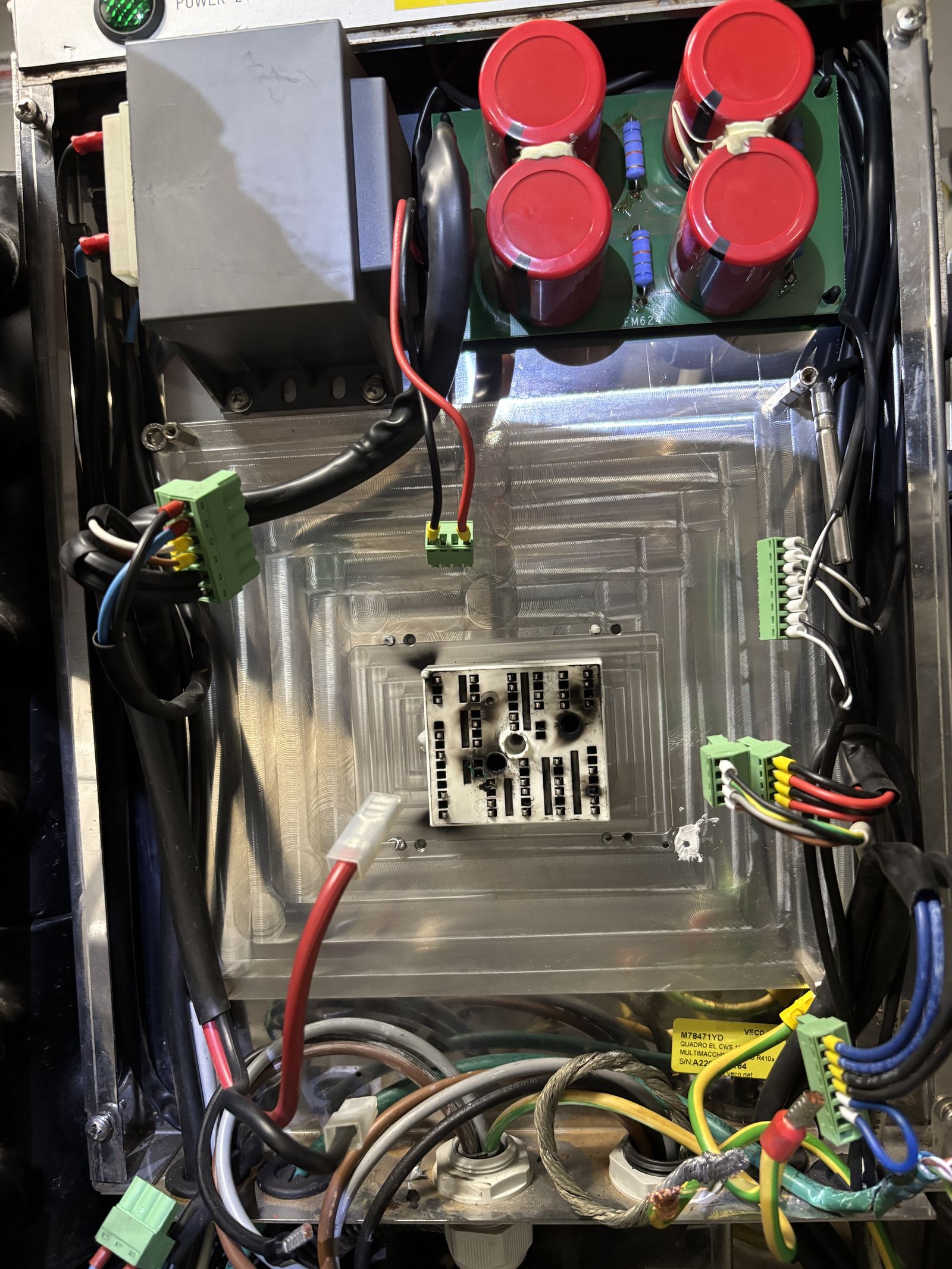
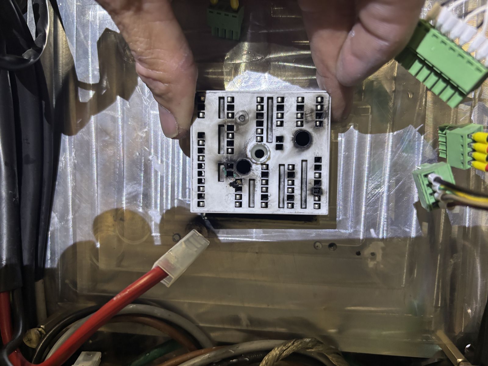
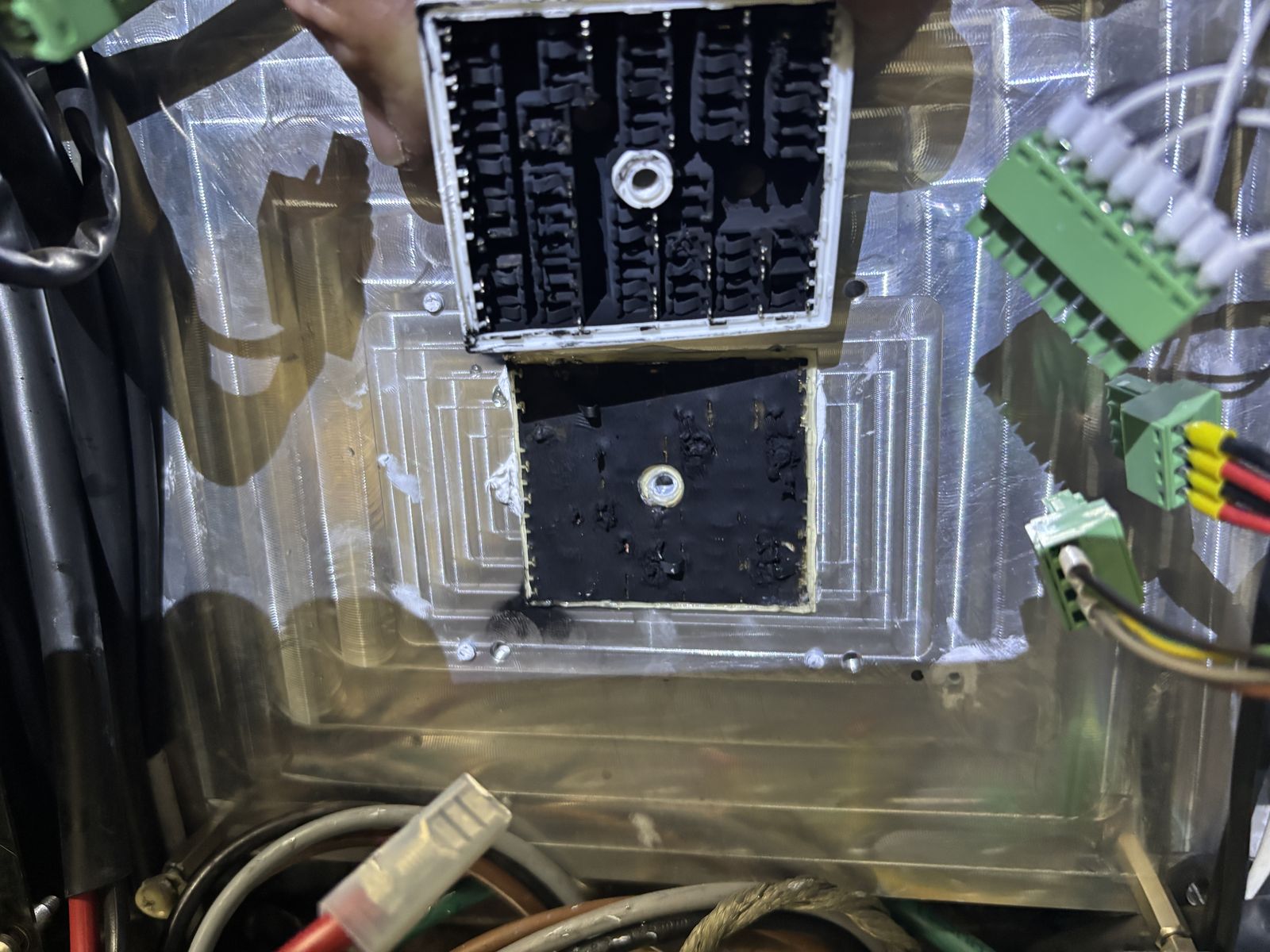
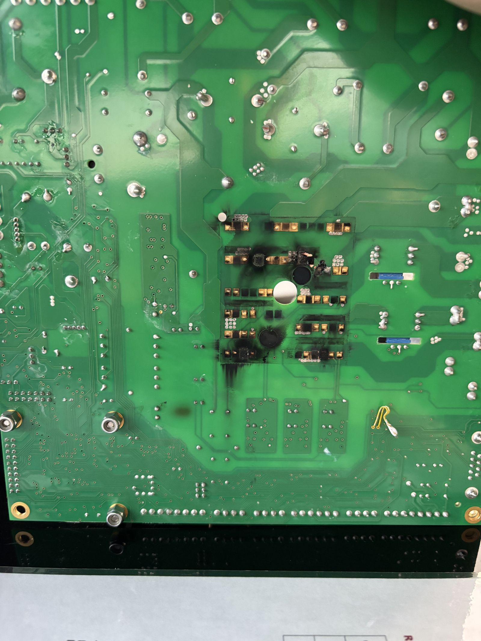
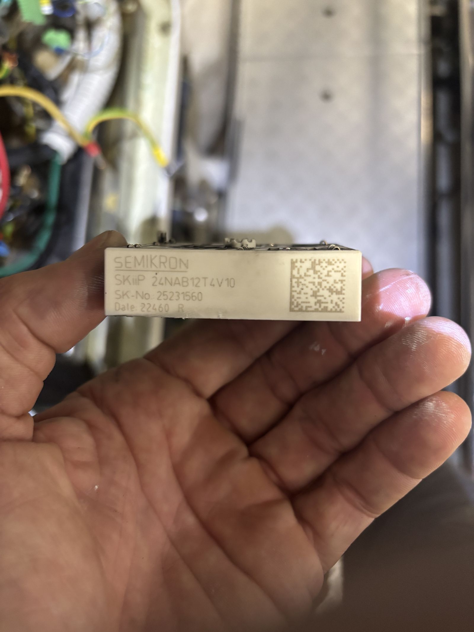
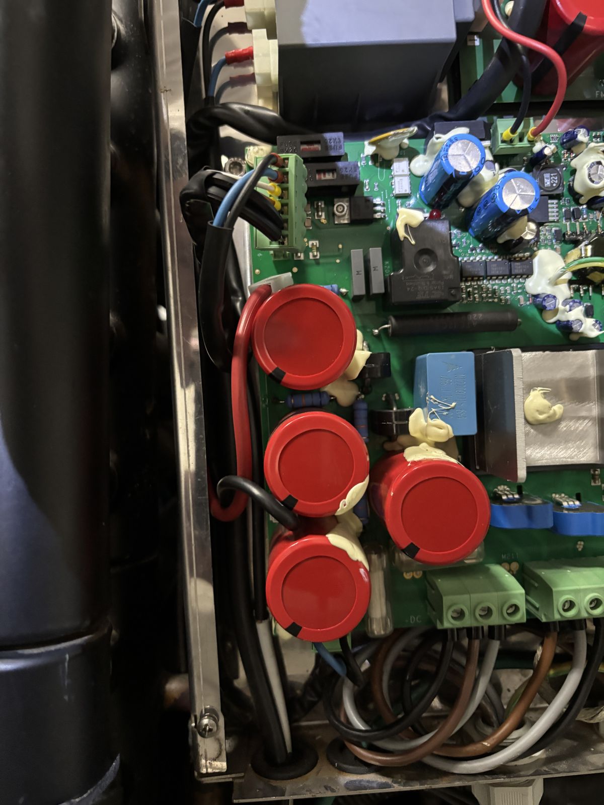
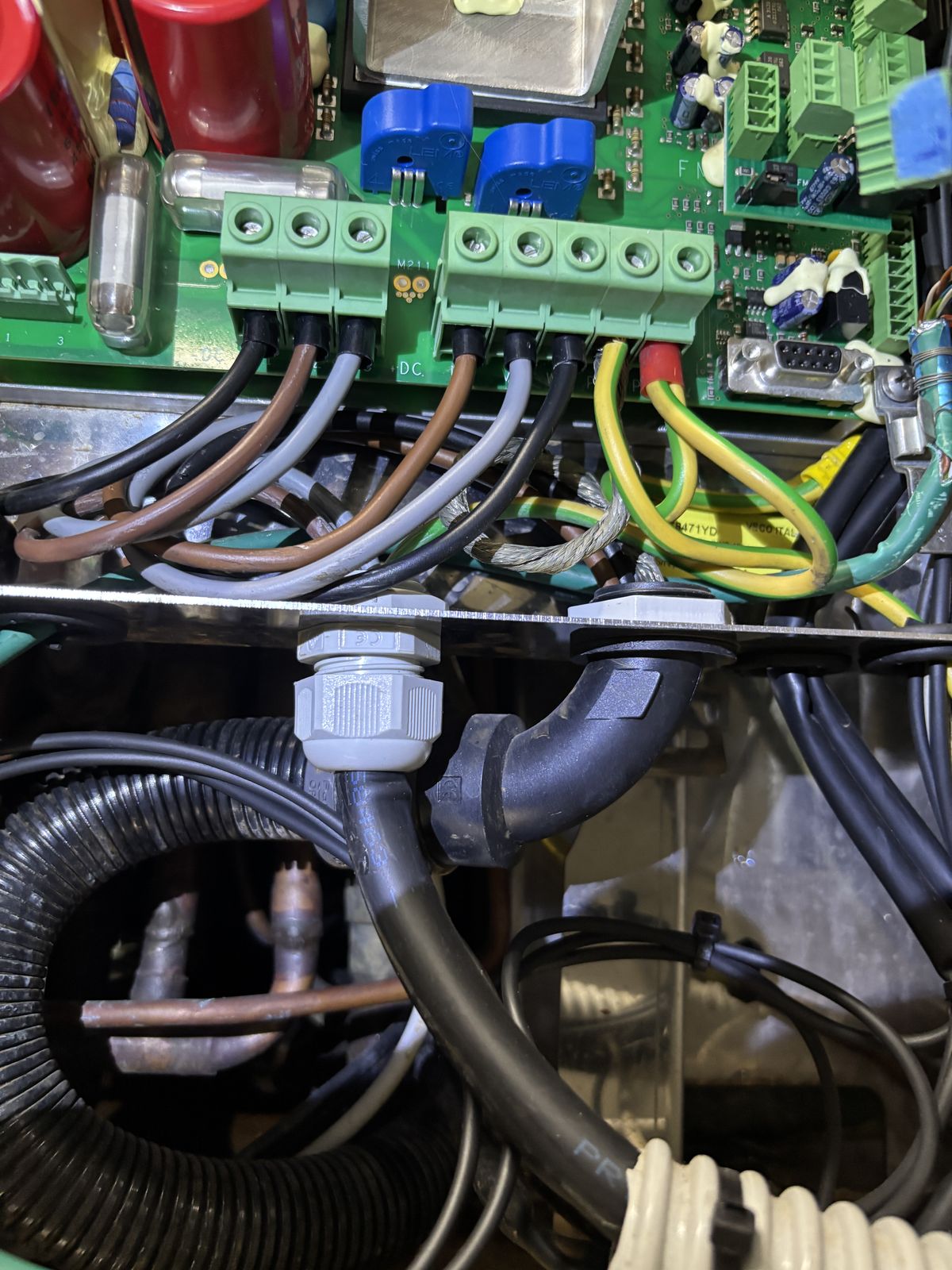
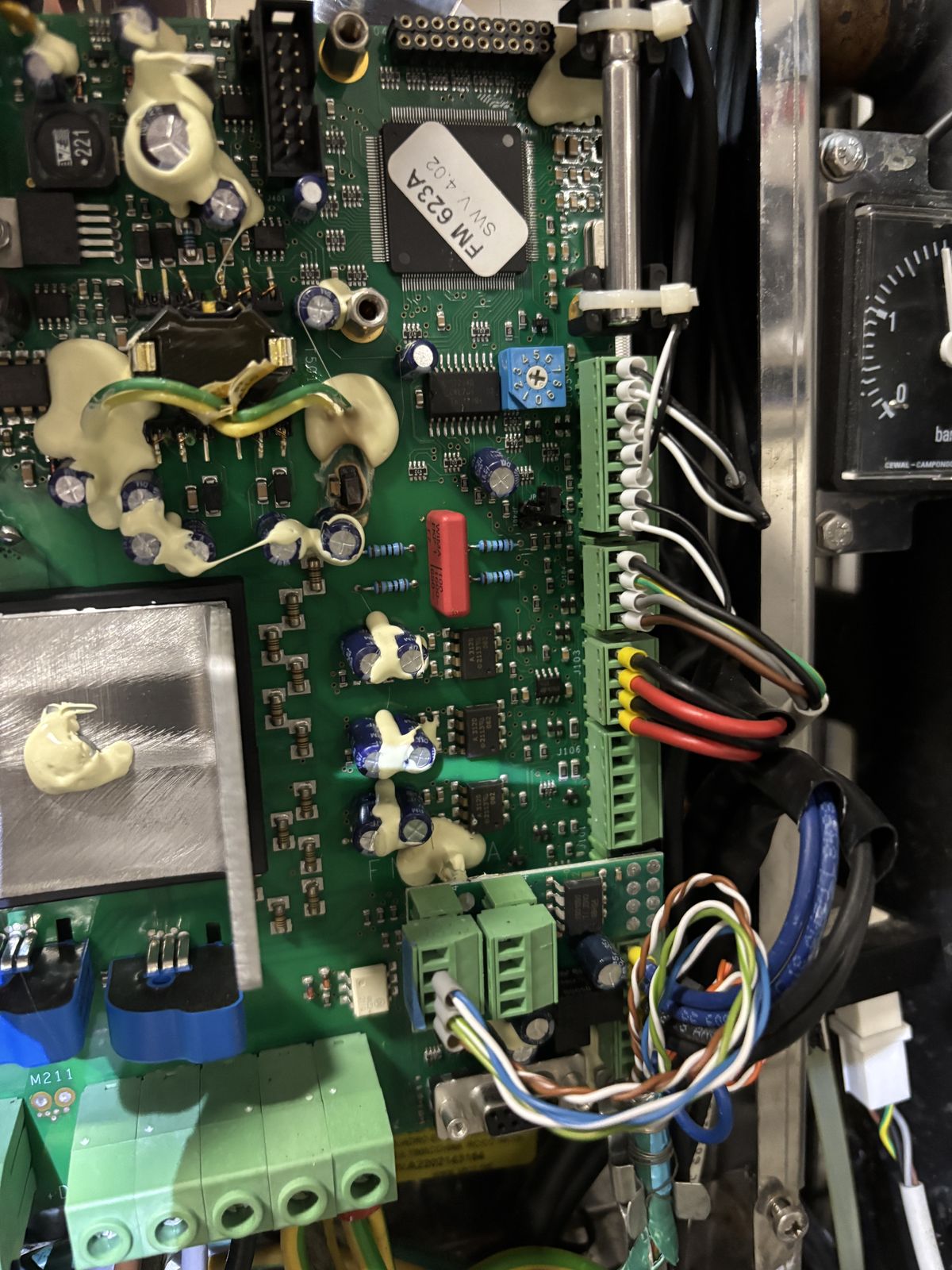
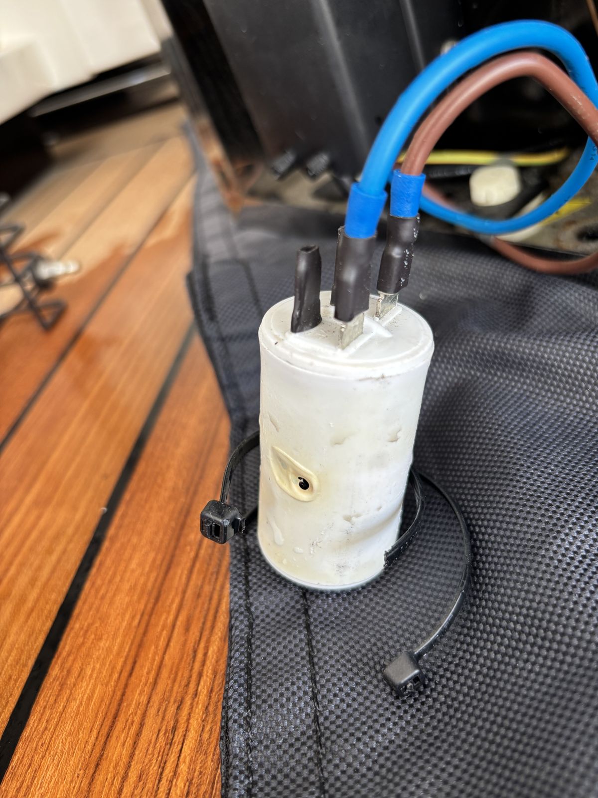
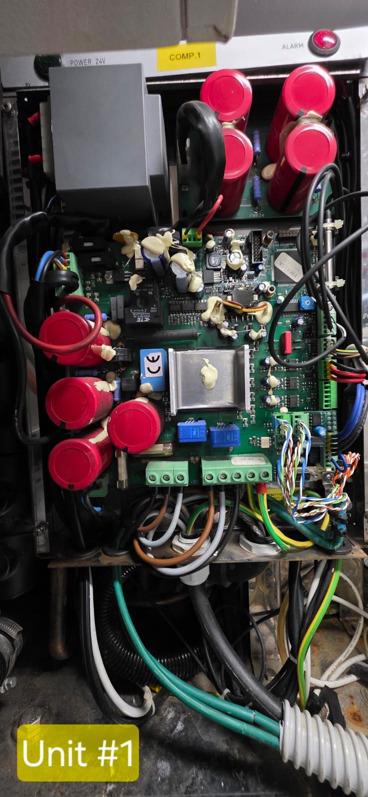
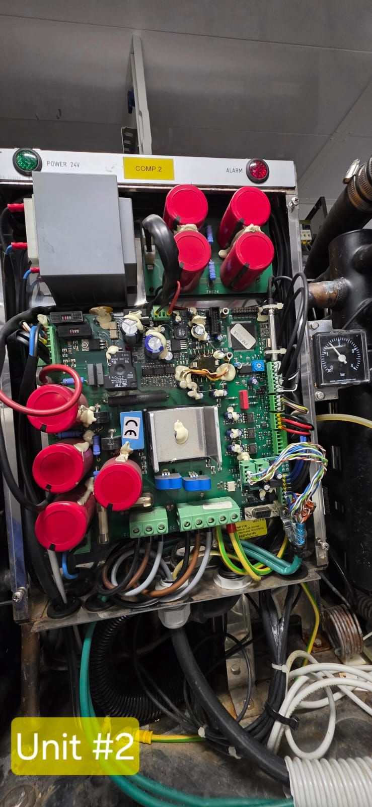
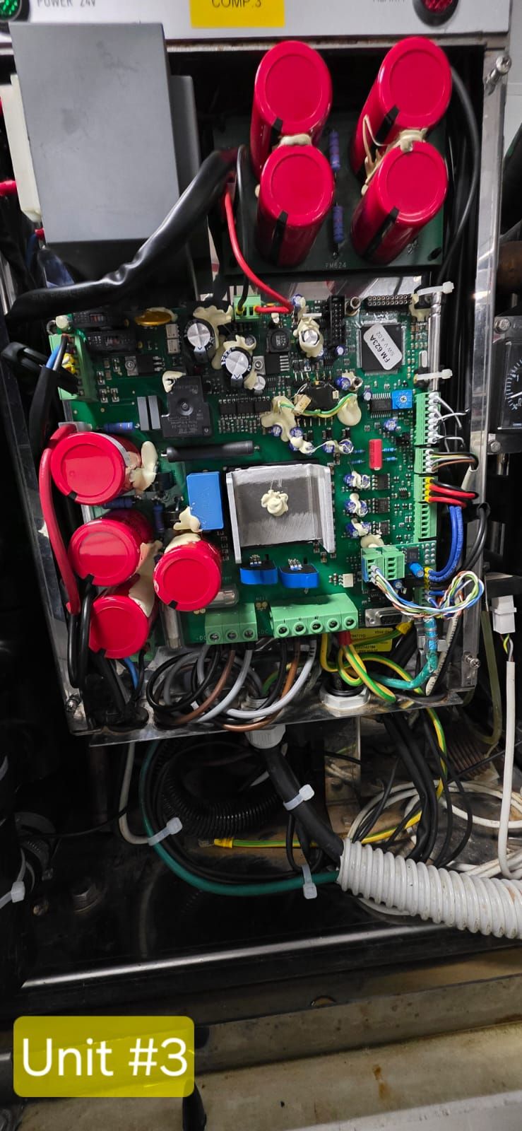
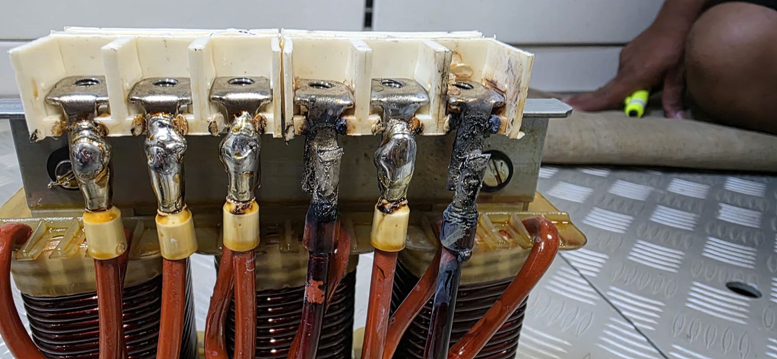
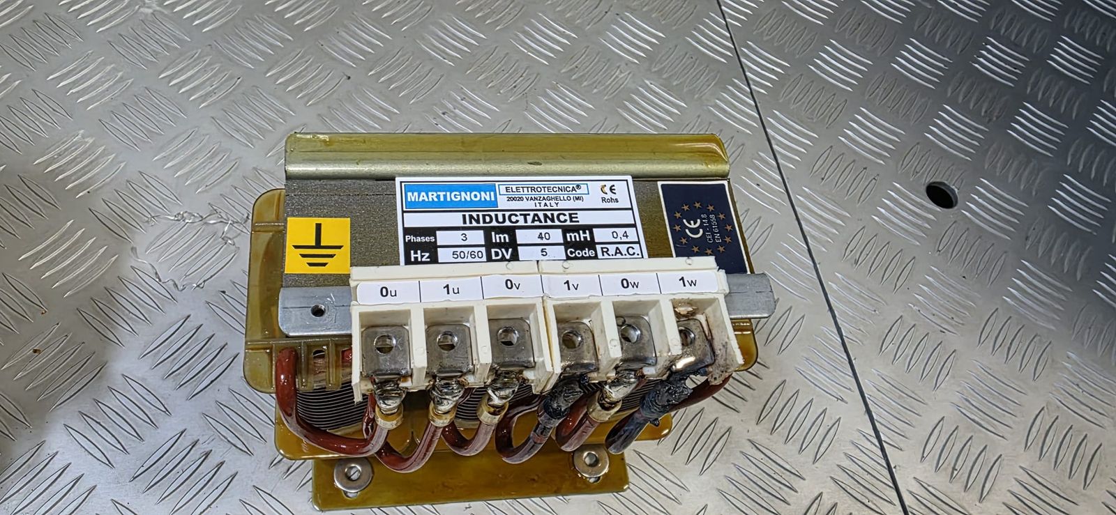
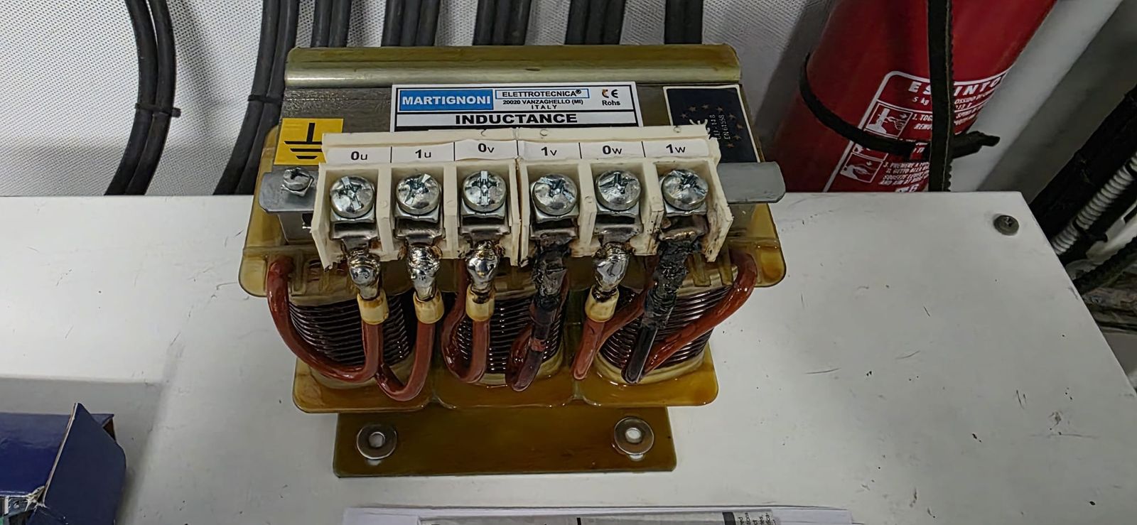
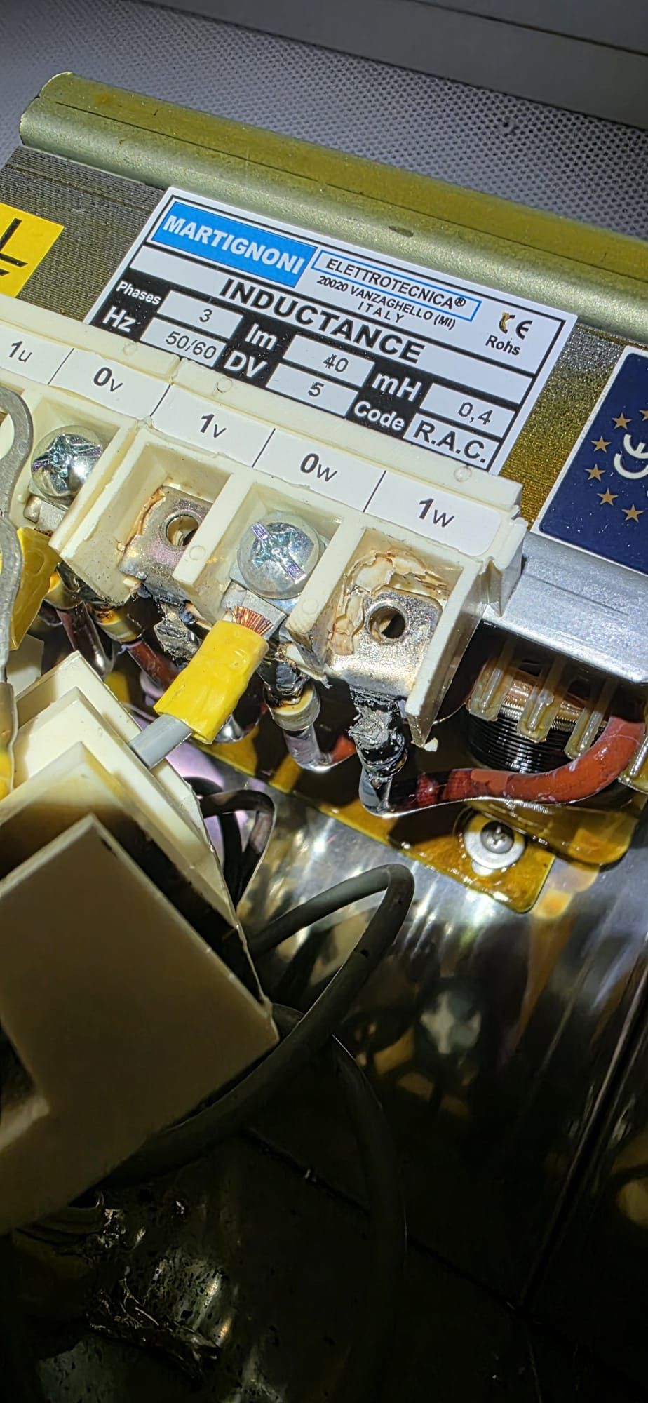
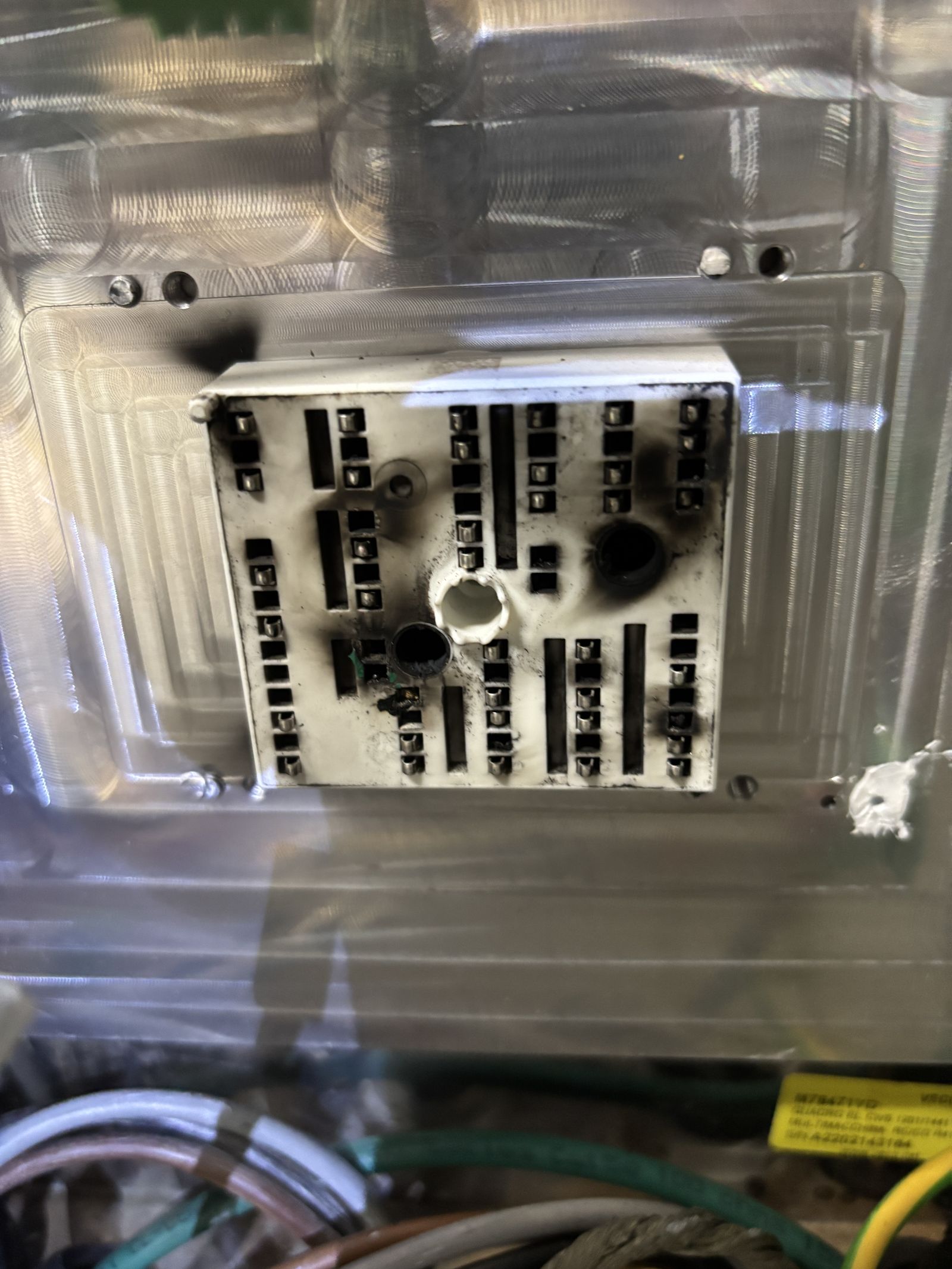
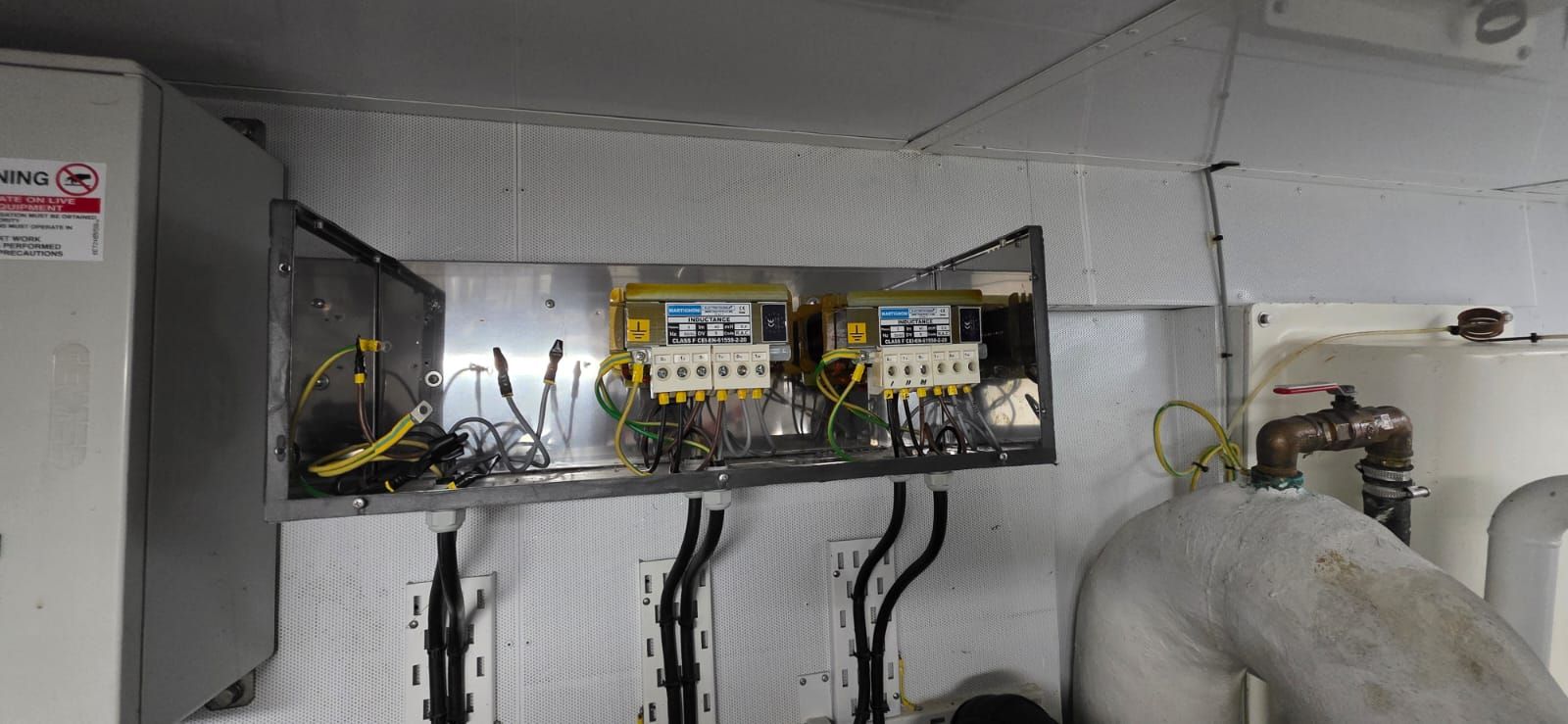
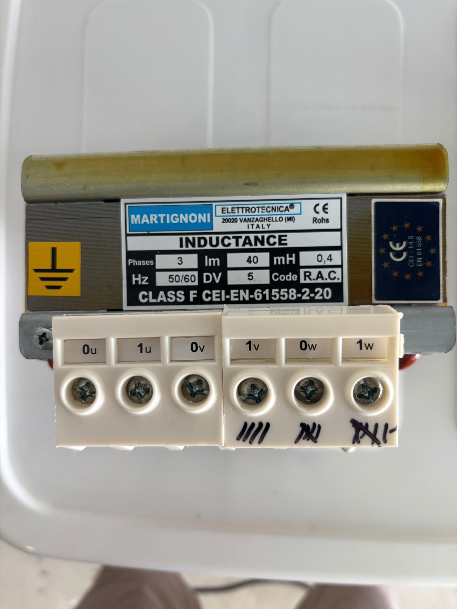
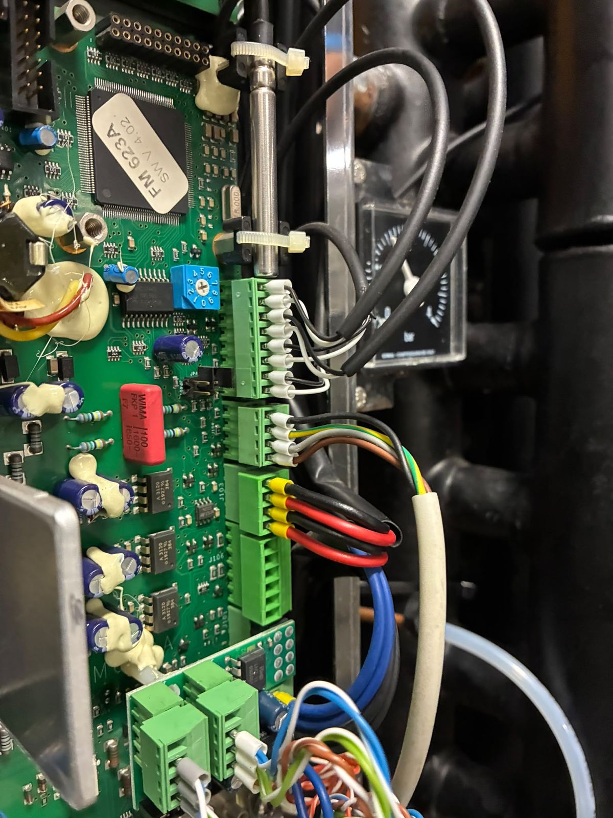
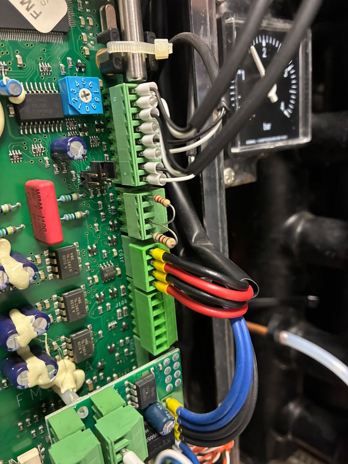
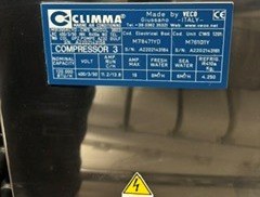
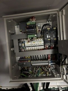
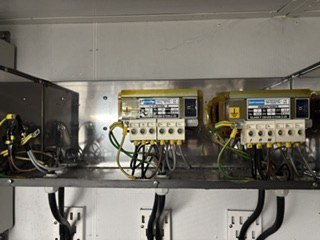
29 Jan 2026. Unit 3 inverter enclosure: scorched IGBT power module.29 Jan 2026. Unit 3 inverter: power module on its heatsink, scorch marks visible, connectors unplugged.29 Jan 2026. Unit 3 inverter: heatsink after the power module was lifted, charred thermal pad.29 Jan 2026. Underside of the unit 3 inverter circuit board: burn mark through the board.29 Jan 2026. Label of the Semikron SKiiP 24NAB12 power module removed from the unit 3 drive.29 Jan 2026. Unit 3 inverter cabinet: control board and DC-link capacitor bank (red capacitors).29 Jan 2026. Unit 3 inverter cabinet: DC terminals and wiring below the board.29 Jan 2026. Unit 3 inverter control board, close view of components and terminal blocks.28 May 2026. A motor-run capacitor removed from the plant with a ruptured casing. Which motor it served is not recorded on the photo.29 Jun 2026. Unit 1 inverter cabinet open during the independent inspection.29 Jun 2026. Unit 2 inverter cabinet open during the independent inspection.29 Jun 2026. Unit 3 inverter cabinet open during the independent inspection.29 Jun 2026. Unit 3 line reactor: charred W-phase terminal.29 Jun 2026. Line reactor removed, top view, nameplate and terminal row with the charred W terminal.29 Jun 2026. Line reactors in place, front view, showing W-phase terminal charring.29 Jun 2026. Line reactor terminals 0W/1W close-up, with the Martignoni nameplate.29 Jan 2026. Identification label inside the unit 3 inverter enclosure.29 Jun 2026. Open-frame line reactors mounted beside seawater piping in the machinery space.Aug 2026. Line reactor nameplate: three-phase, 40 A, 0.4 mH (a reactor, not a transformer).14 Aug 2026. Unit 2 inverter board, connector J104: new flow-sensor cable landed.14 Aug 2026. Unit 2 inverter board, connector J104: resistors across the sensor terminals.14 Oct 2026 (as received). Compressor 3 data plate (Climma, made by Veco): unit CWS 1201, 400/3/50, R410A 4.250 kg.14 Oct 2026 (as received). AC plant control box, door open: breakers and control wiring.14 Oct 2026 (as received). Line reactors on a shelf with terminal blocks (state to be confirmed).
Compressors and flow (19)
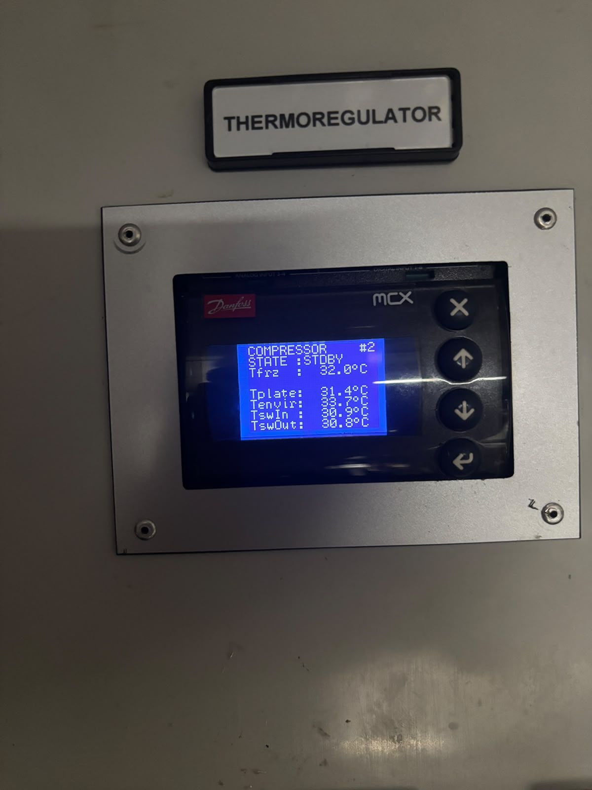
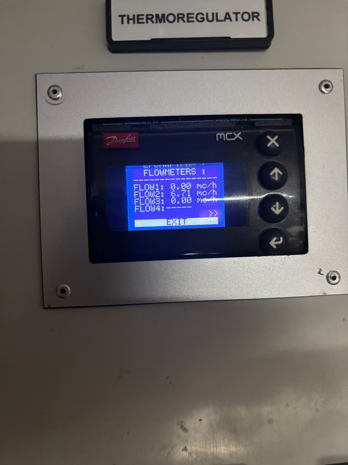
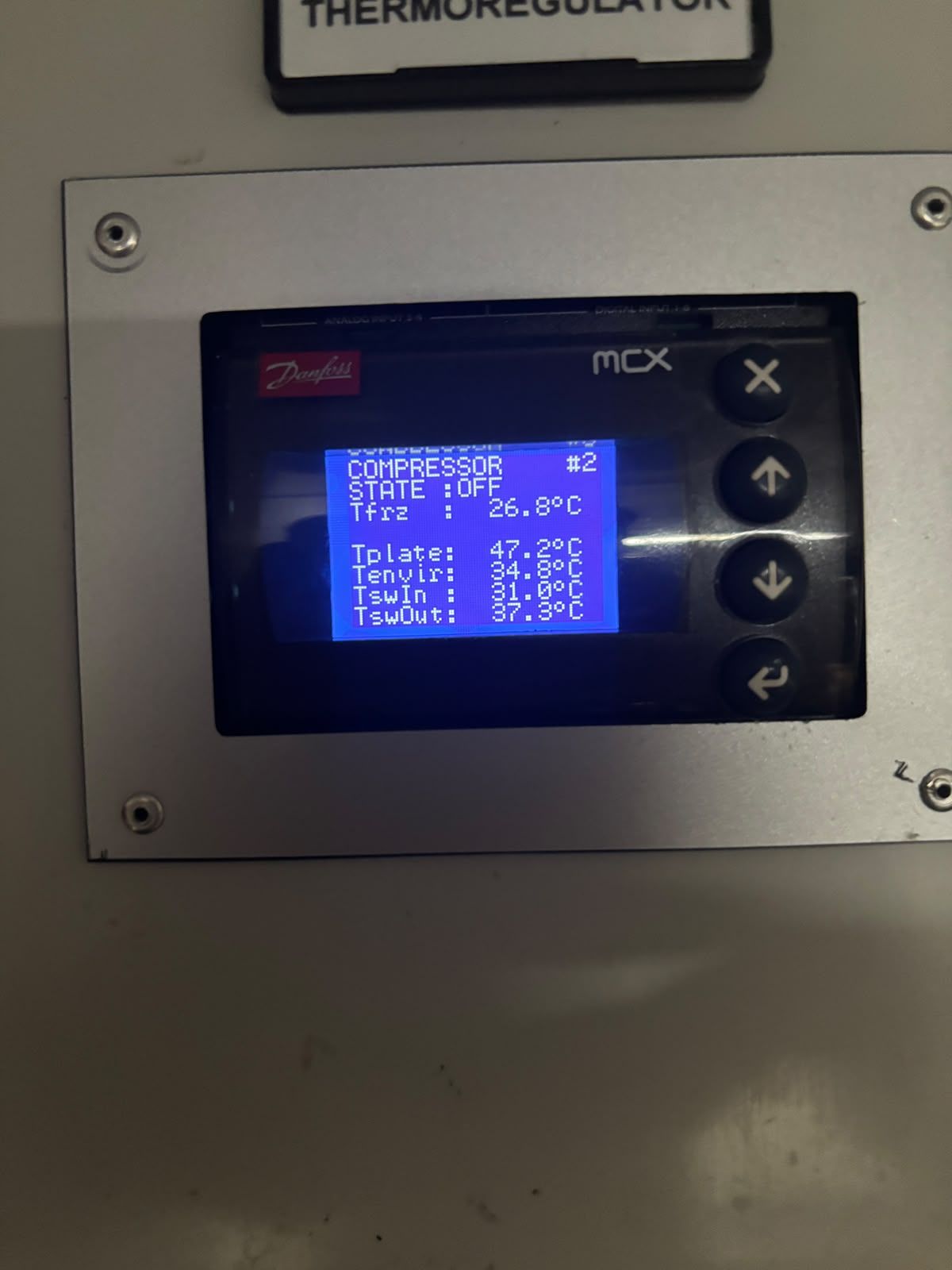
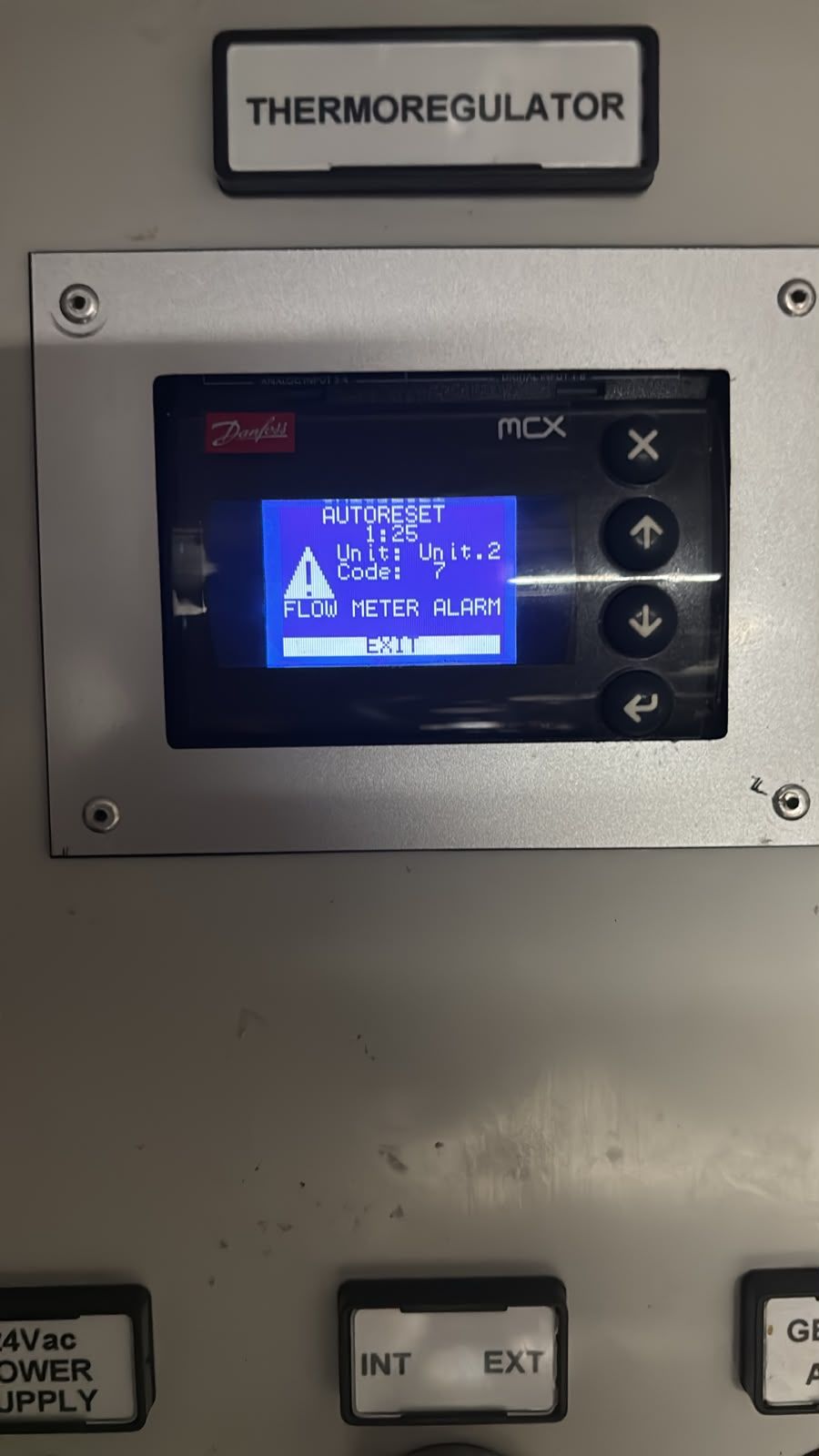
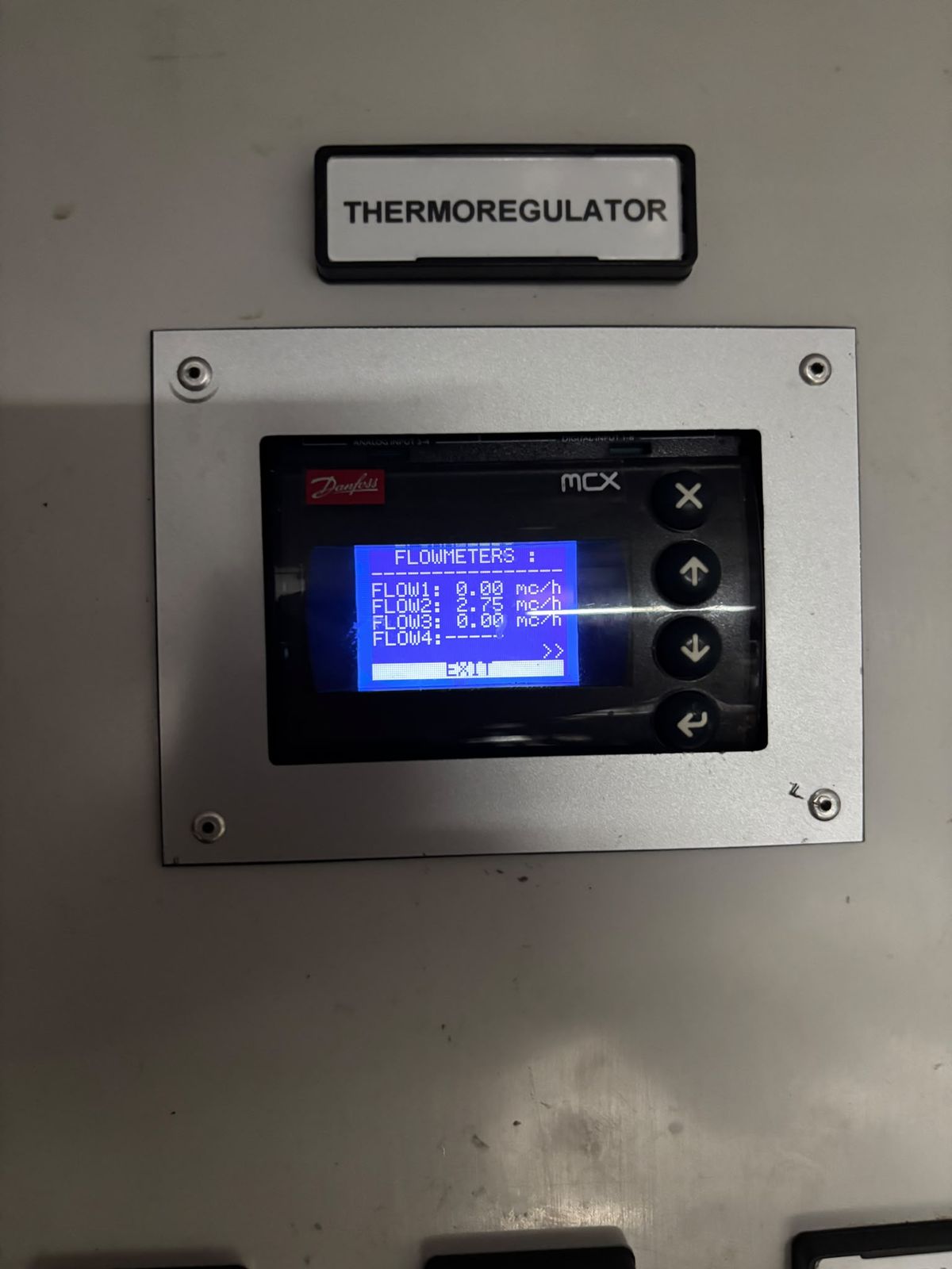
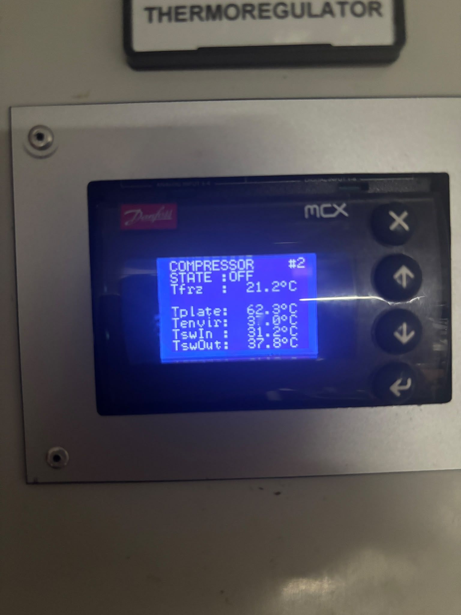
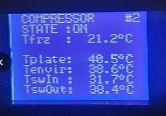
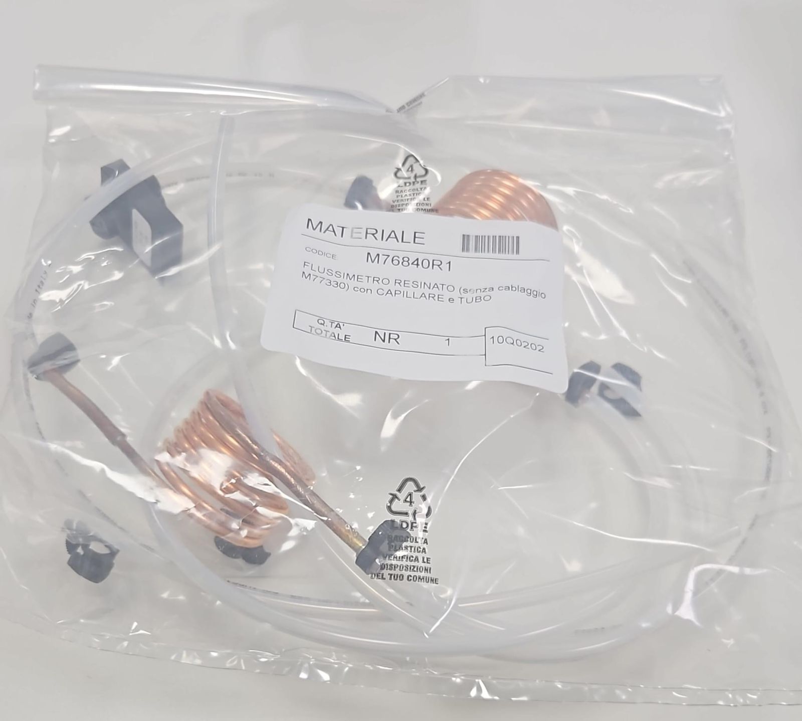
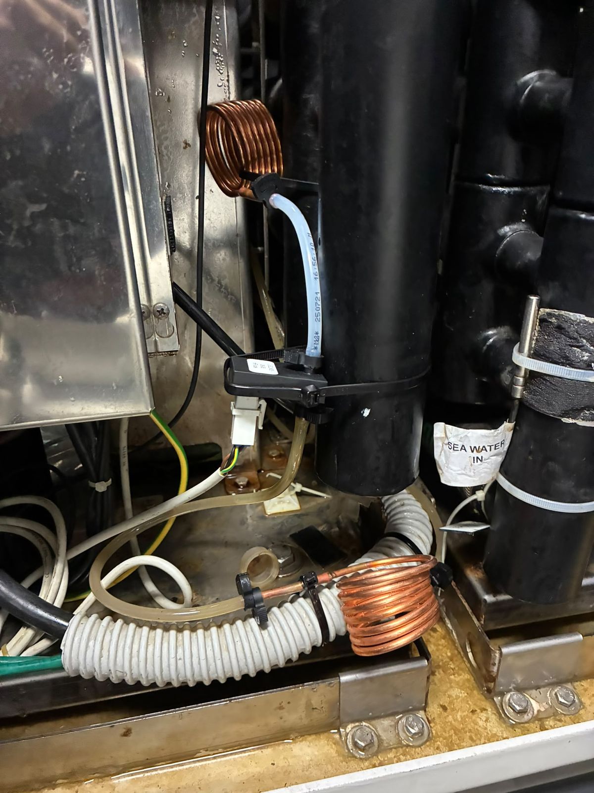
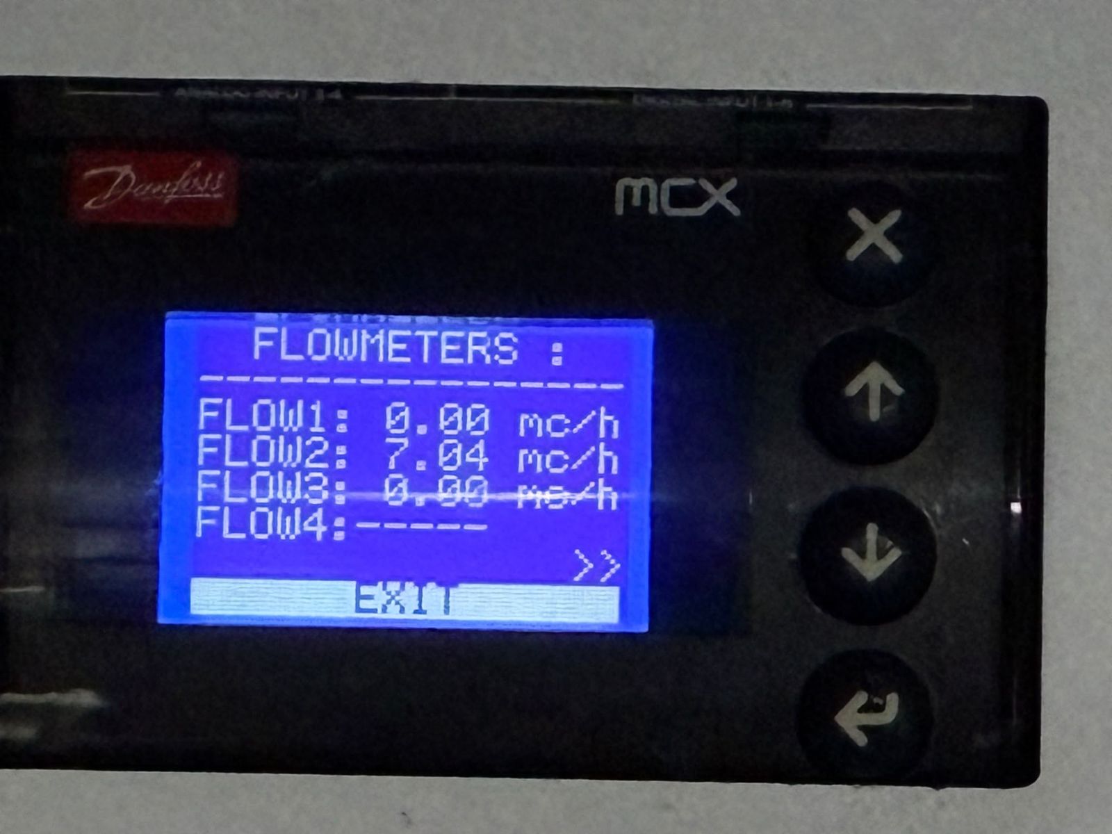
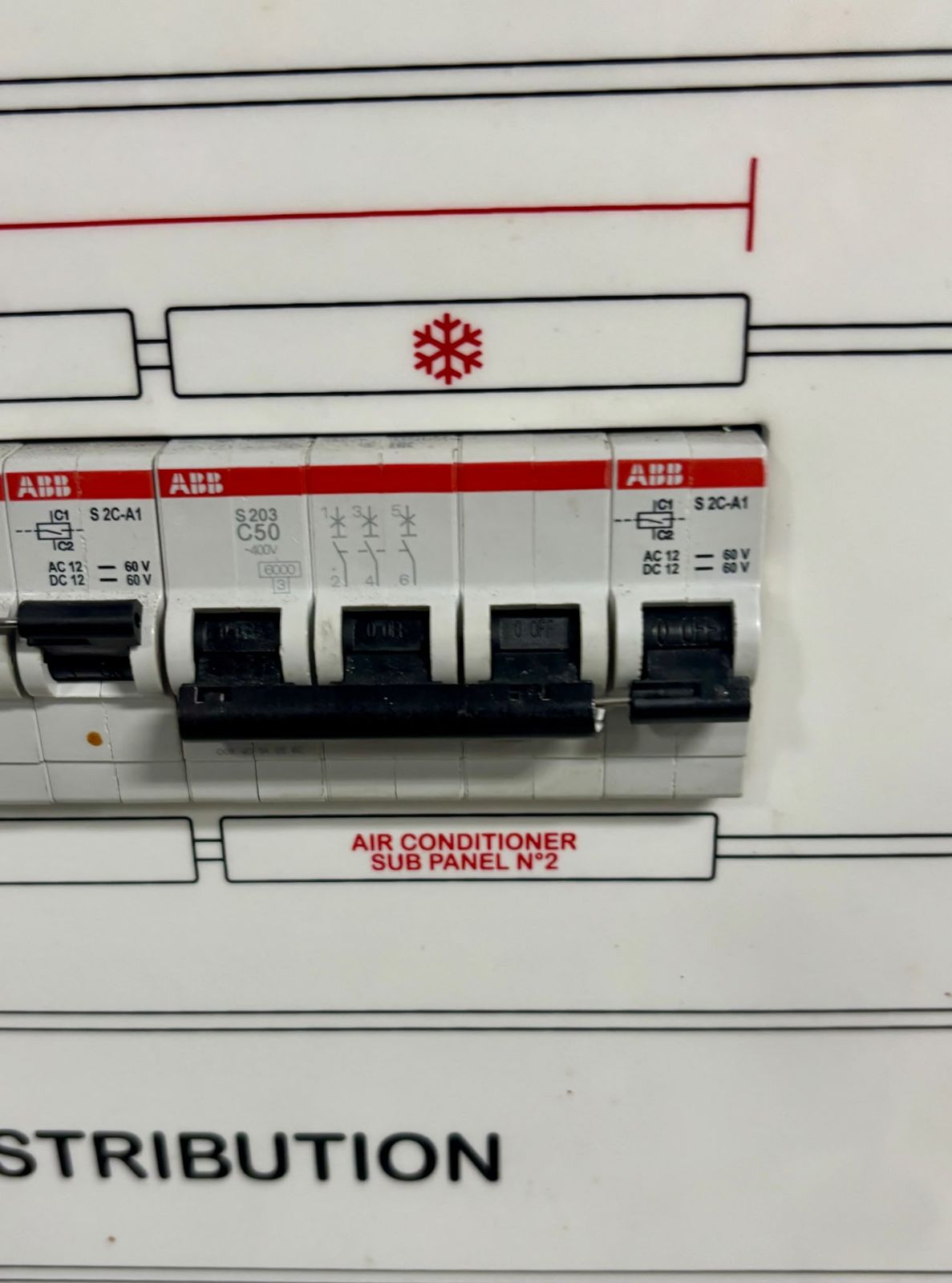
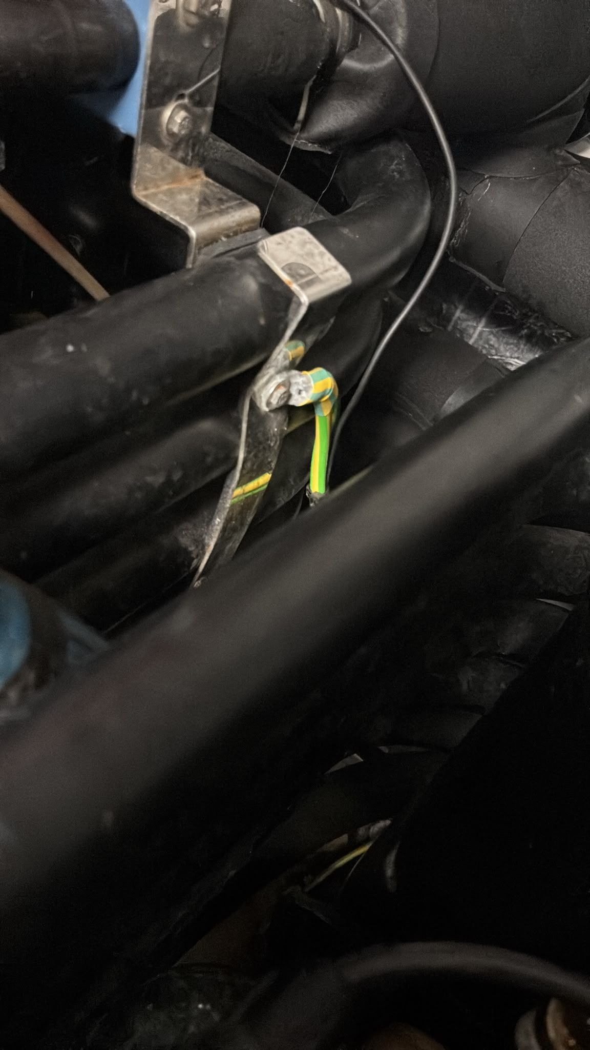
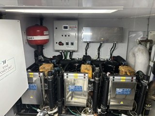
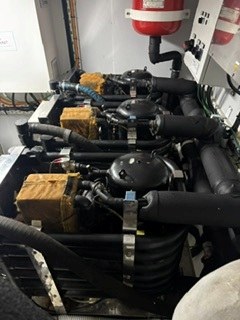
29 Jul 2026, 11:31. Controller screen: unit 2 on standby, inverter plate temperature 31.4 °C as displayed. Reading only, no cause implied.29 Jul 2026, 11:31. Flowmeters screen after a sensor swap: FLOW2 6.71 m³/h as displayed. Reading only, no cause implied.29 Jul 2026, 11:34. Controller screen: unit 2 OFF, inverter plate 47.2 °C as displayed. Reading only, no cause implied.29 Jul 2026, 11:34. Danfoss MCX controller: FLOW METER ALARM, code 7, unit 2. Reading only, no cause implied.29 Jul 2026, 15:33. Video (40 s, trimmed): unit 2 running, inverter plate temperature rising from 44.5 °C as displayed. Reading only, no cause implied.29 Jul 2026, 15:33. Video (23 s): unit 2 running, plate temperature about 49.0 °C and rising as displayed. Reading only, no cause implied.29 Jul 2026, 15:33. Video (37 s): unit 2 running, plate temperature about 50.5 °C and rising as displayed. Reading only, no cause implied.29 Jul 2026, 15:33. Flowmeters screen: FLOW1 0.00, FLOW2 2.75, FLOW3 0.00 m³/h as displayed. Reading only, no cause implied.29 Jul 2026, 15:33. Video (3 s): flowmeters screen, all flows 0.00 m³/h as displayed. Reading only, no cause implied.29 Jul 2026, 15:33. Controller screen: unit 2 compressor OFF, inverter plate 62.3 °C as displayed. Reading only, no cause implied.3 Aug 2026, 12:12. Unit 2 compressor running after fuse replacement: plate 40.5 °C, Tenvir 38.6 °C, TswIn 31.7 °C, TswOut 38.4 °C as displayed. Reading only, no cause implied.7 Aug 2026. Replacement flowmeter (part M76840R1) as delivered, in its bag.14 Aug 2026. New flowmeter fitted at the sea-water inlet of unit 2.14 Aug 2026. Flowmeters screen after the new sensor: FLOW2 7.04 m³/h as displayed (rated flow noted as 6 m³/h). Reading only, no cause implied.19 Aug 2026, 13:00. AC sub-panel 2: three-pole breaker (ABB S203 C50) in the tripped position.19 Aug 2026. Video (14 s, sound removed): unit 2 compressor start attempt; the main AC breaker trips.19 Aug 2026. Earth point used as the reference for compressor insulation tests.14 Oct 2026 (as received). The three chiller modules installed in the machinery space, with pumps and piping.14 Oct 2026 (as received). Compressors from above, with yellow terminal boxes (to be confirmed) and insulated piping.
Sea water, chilled loop and strainers (14)
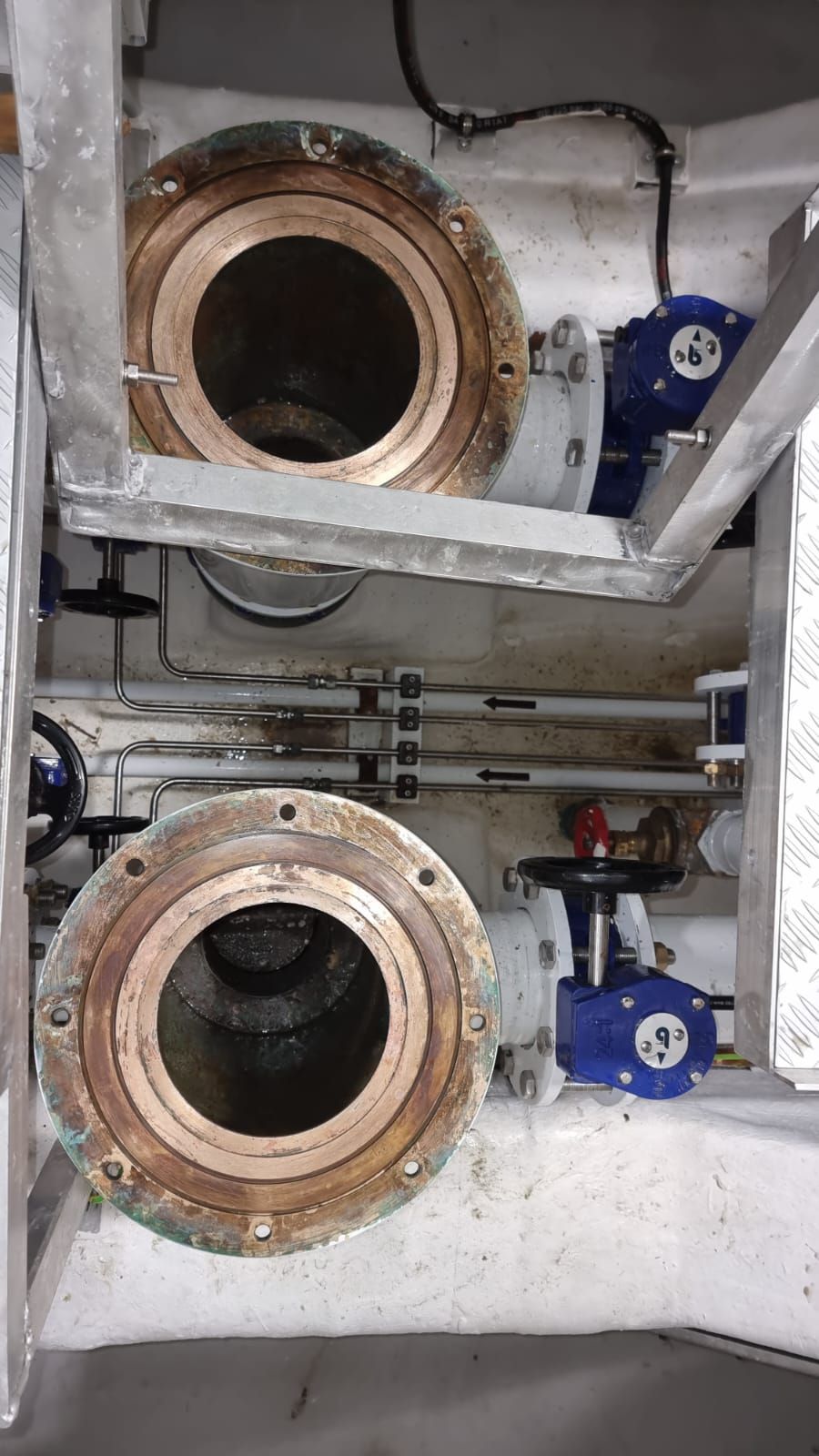
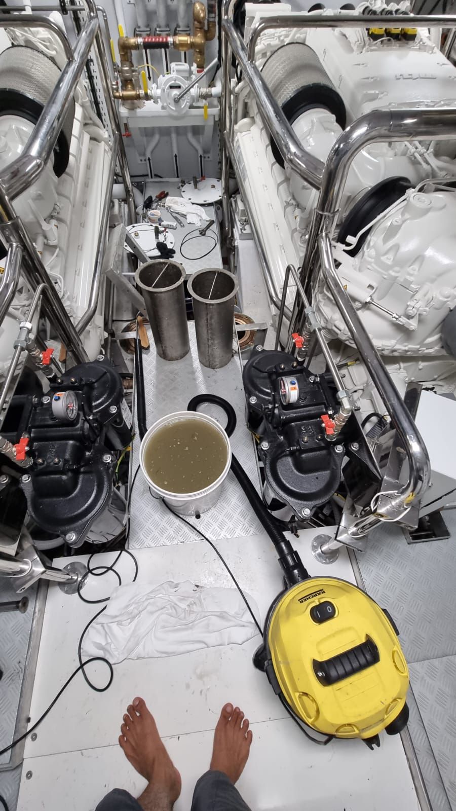
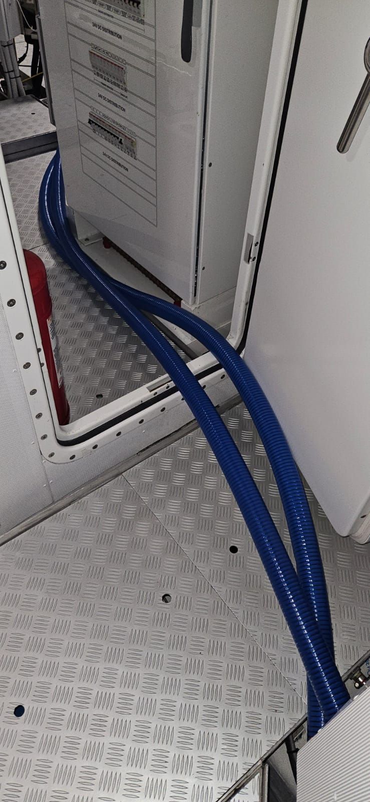
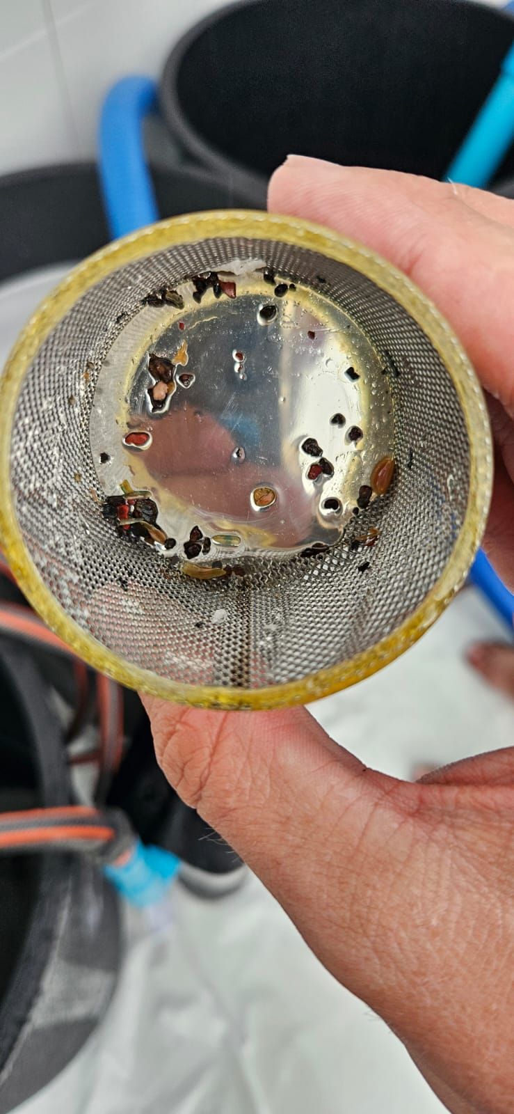
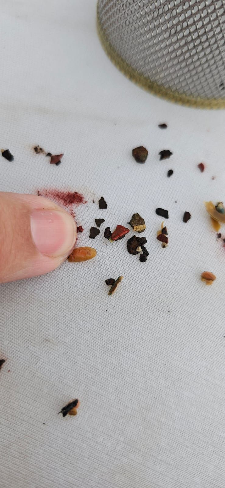
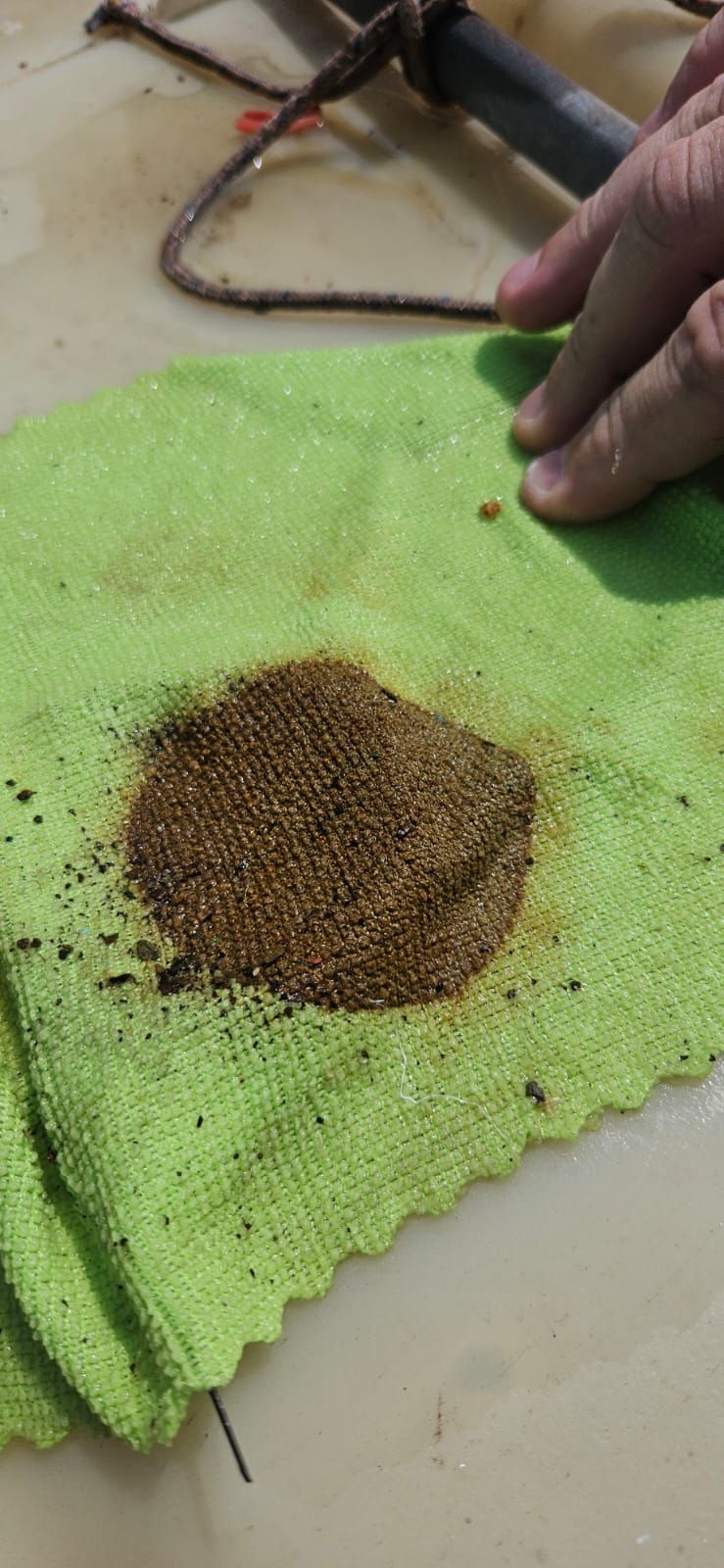
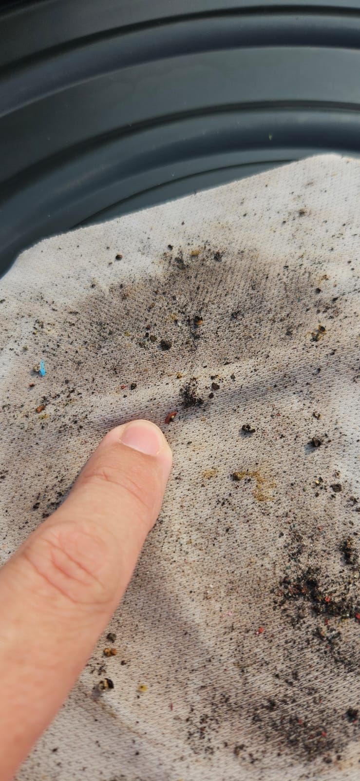
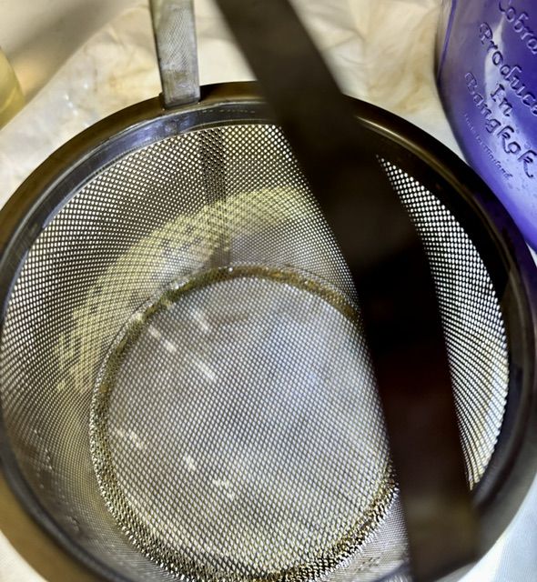
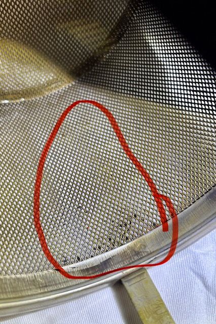
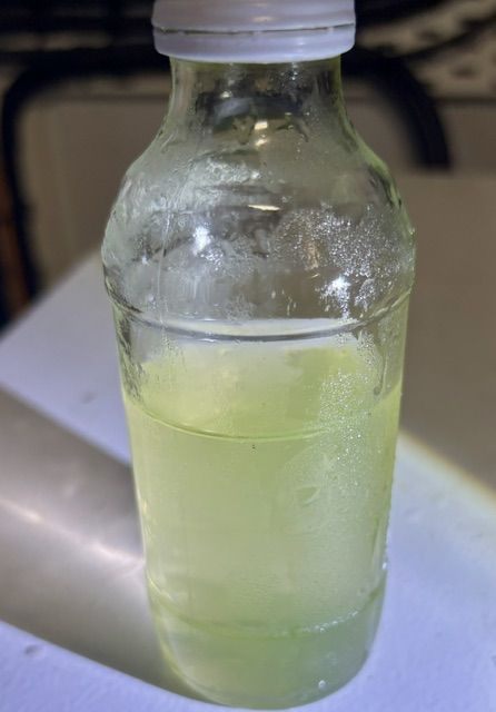
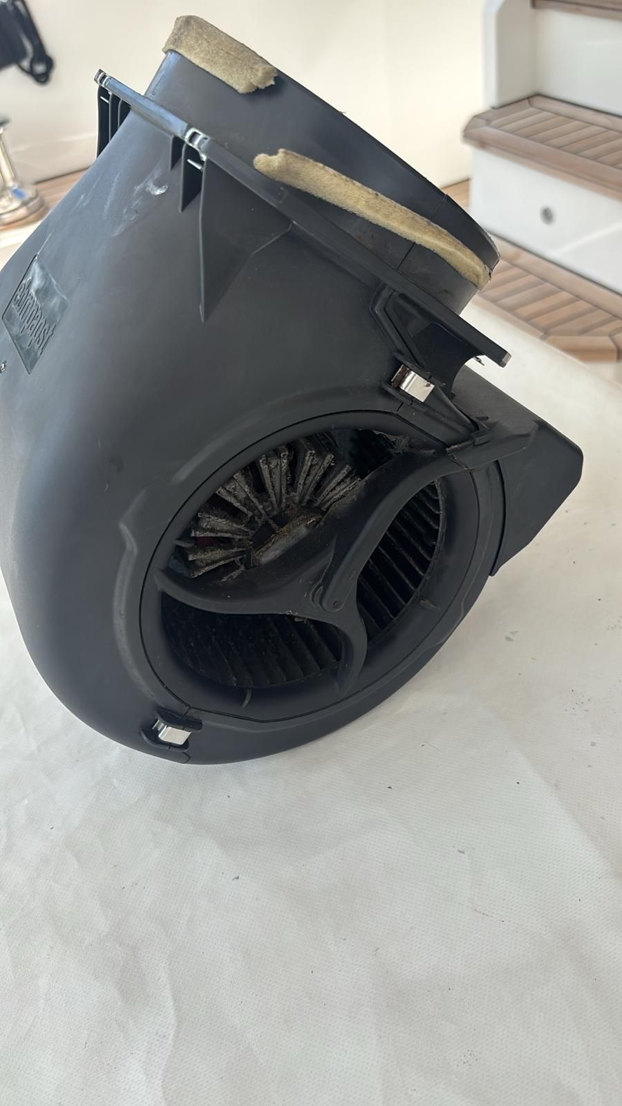
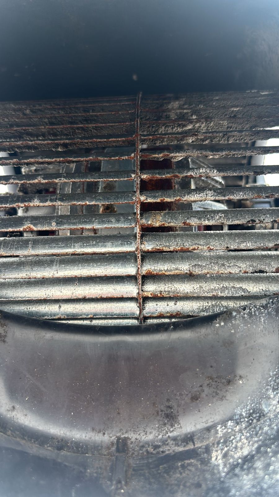
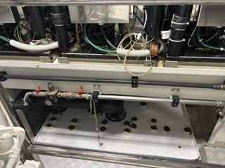
8 Dec 2023. Two sea chests opened for inspection.8 Dec 2023. Engine room during a seawater-system flush, with a bucket of water beside the pumps.8 Feb 2024. Blue hoses routed past the DC panel, Feb 2024 (purpose to be confirmed).10 Feb 2024. AC strainer basket removed and held up to the light.10 Feb 2024. Debris recovered from an AC strainer, held in a palm.9 Feb 2024. Sediment recovered on a cloth during the chilled-water loop flush.10 Feb 2024. Sludge and particles from the chilled (fresh-water) loop.18 Oct 2024. Video (24 s, sound removed): water at a sea-chest flange.25 Jun 2026. Chilled-loop strainer with granular sediment.25 Jun 2026. Chilled-loop strainer mesh with dark grit (circled).25 Jun 2026. Sealed sample of chilled-loop water and glycol, kept for analysis.2 Sep 2026. Cabin fan-coil blower unit removed, showing the condition of the impeller housing.2 Sep 2026. Cabin fan-coil blower grille, close-up of rust.14 Oct 2026 (as received). Underside of a module: piping and valves; tray below (purpose to be confirmed).
Controller alarms (Danfoss MCX) (13)
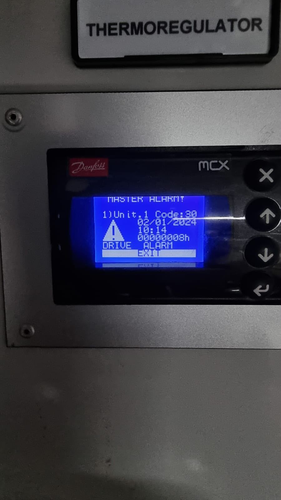
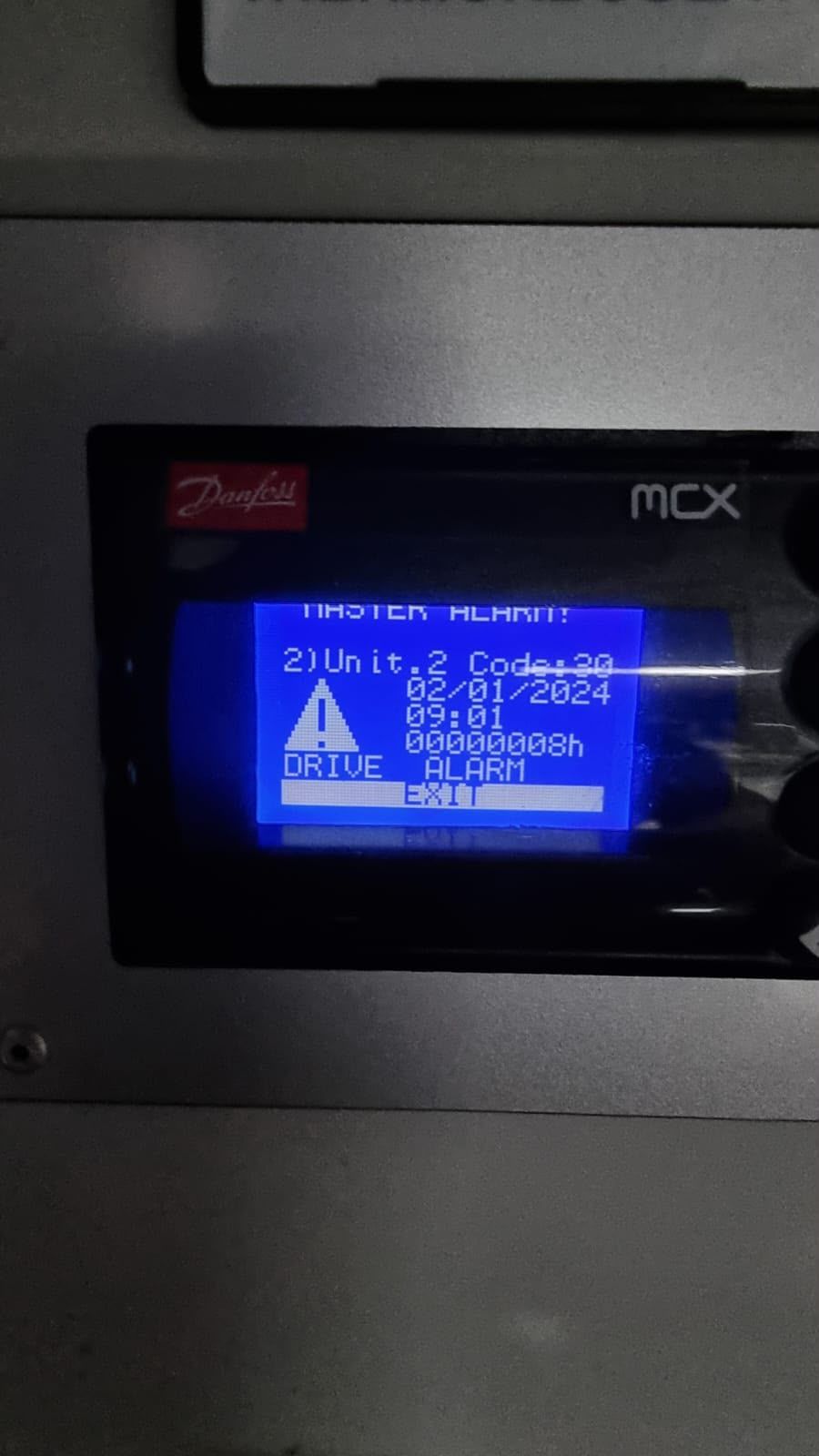
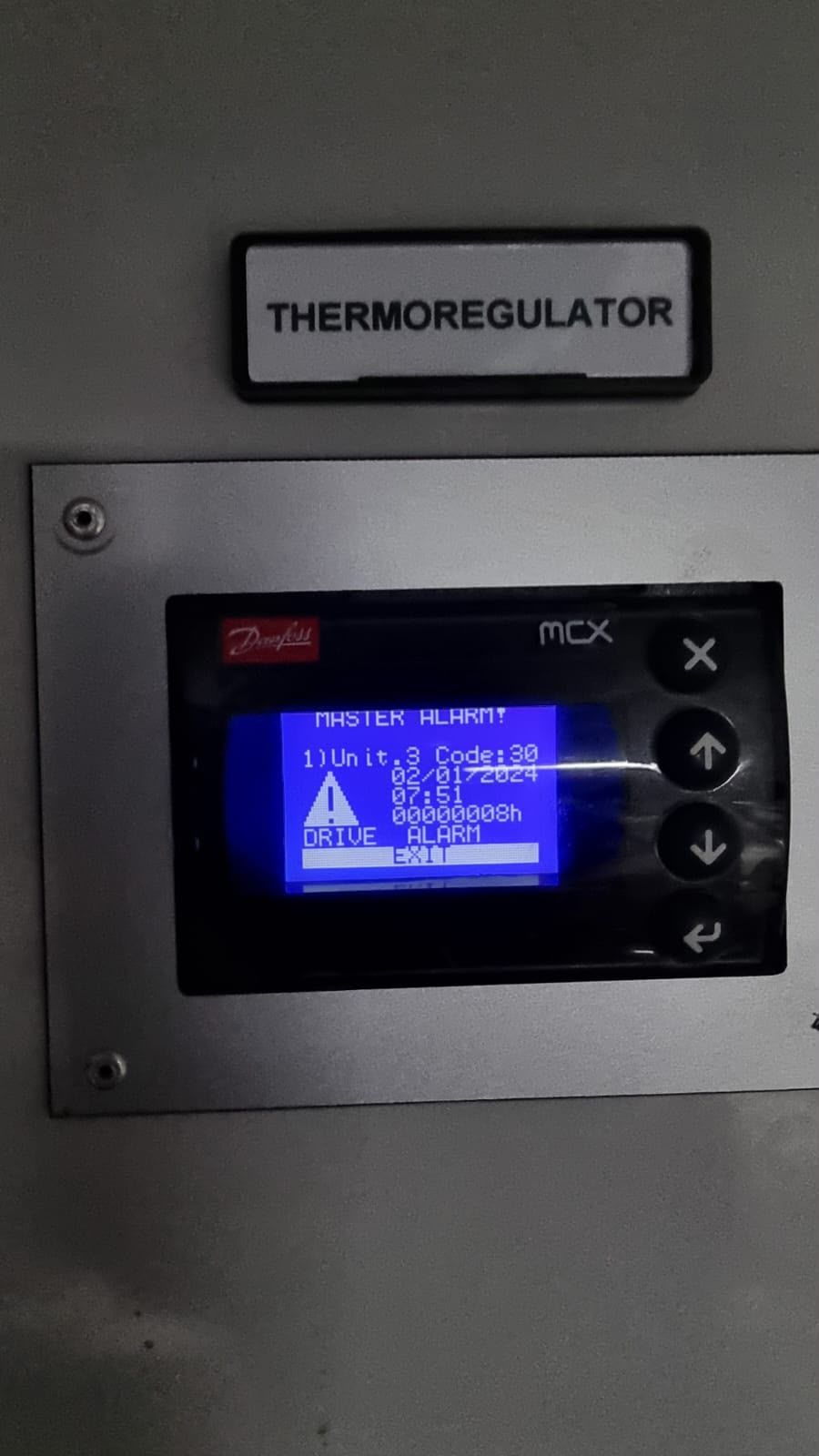
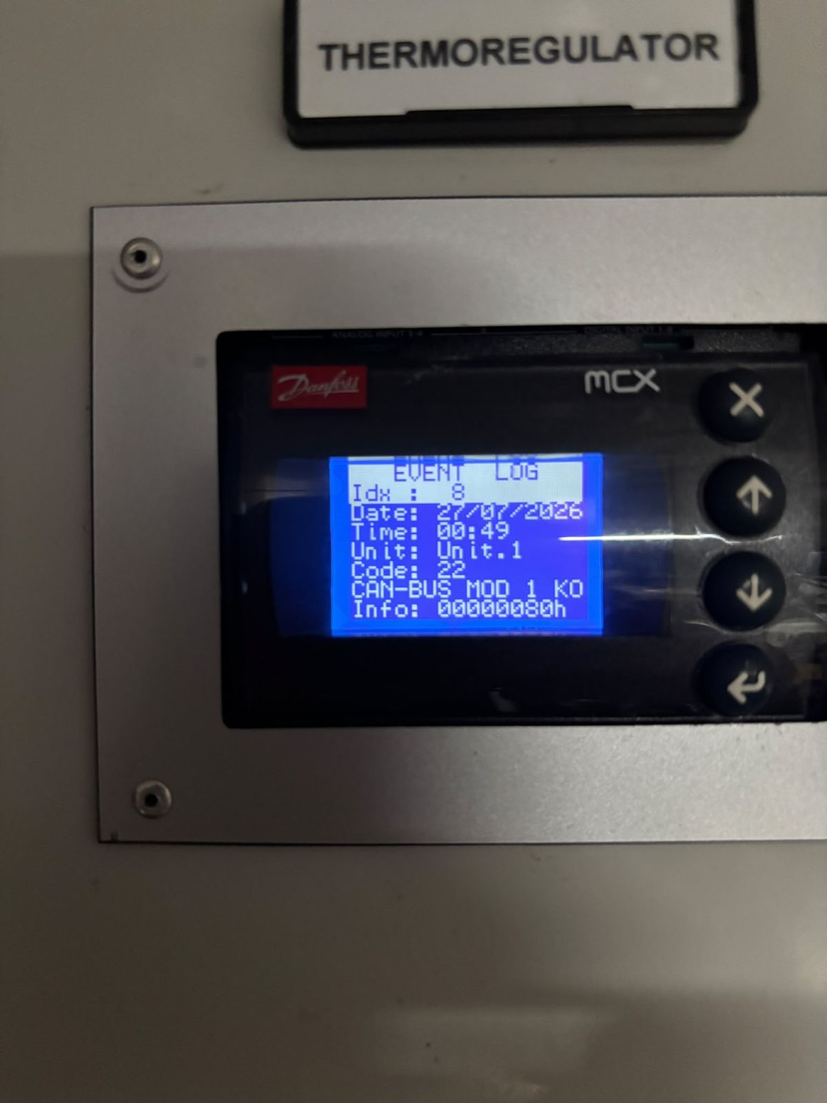
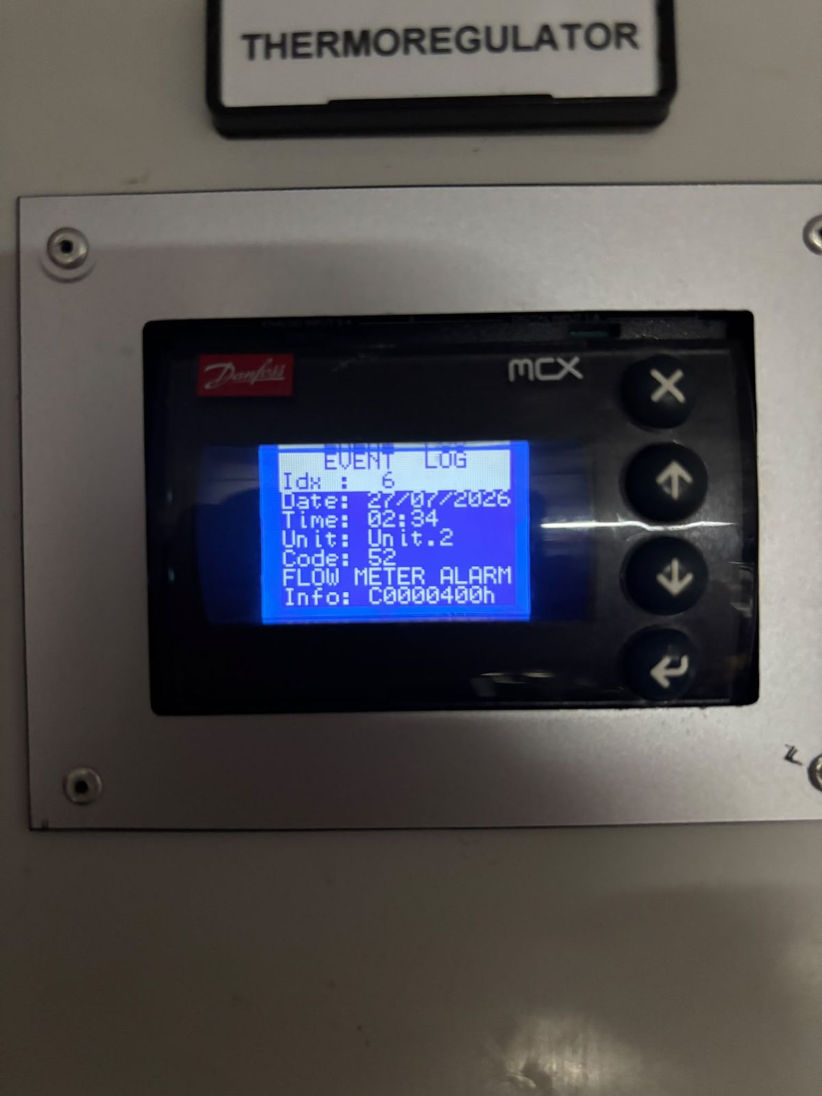
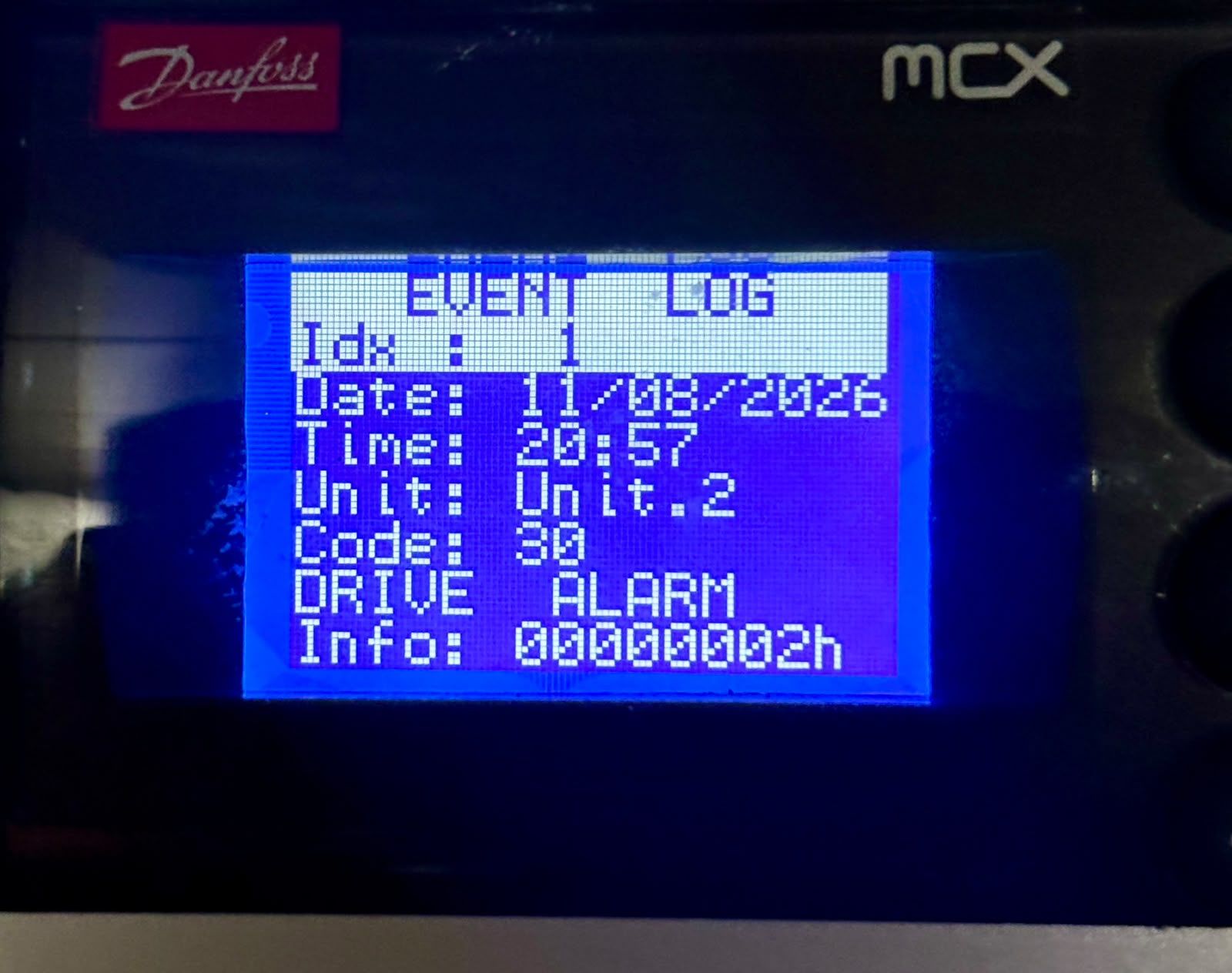
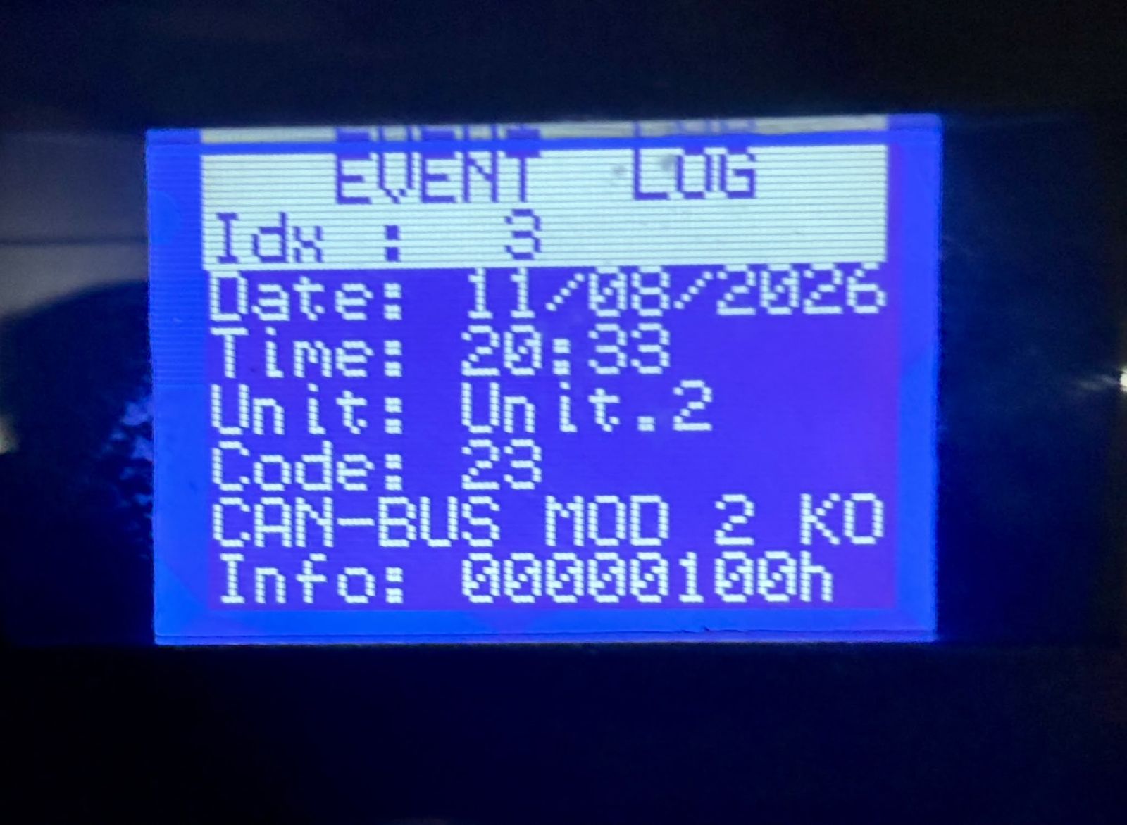
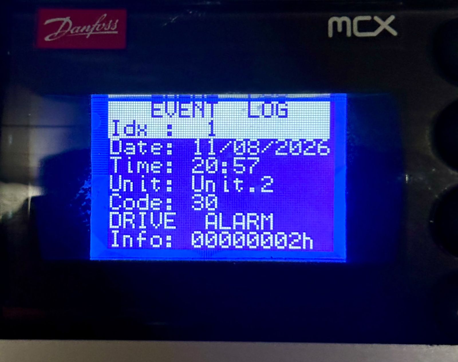
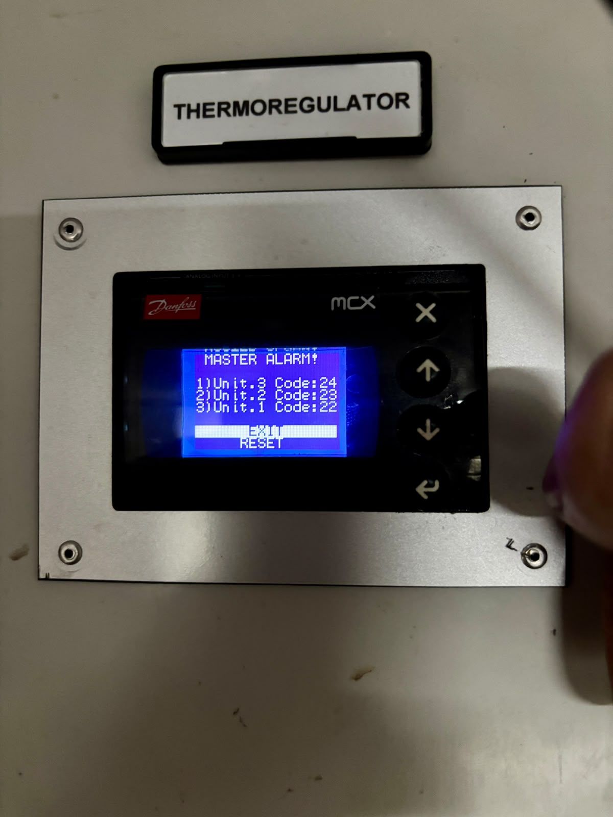
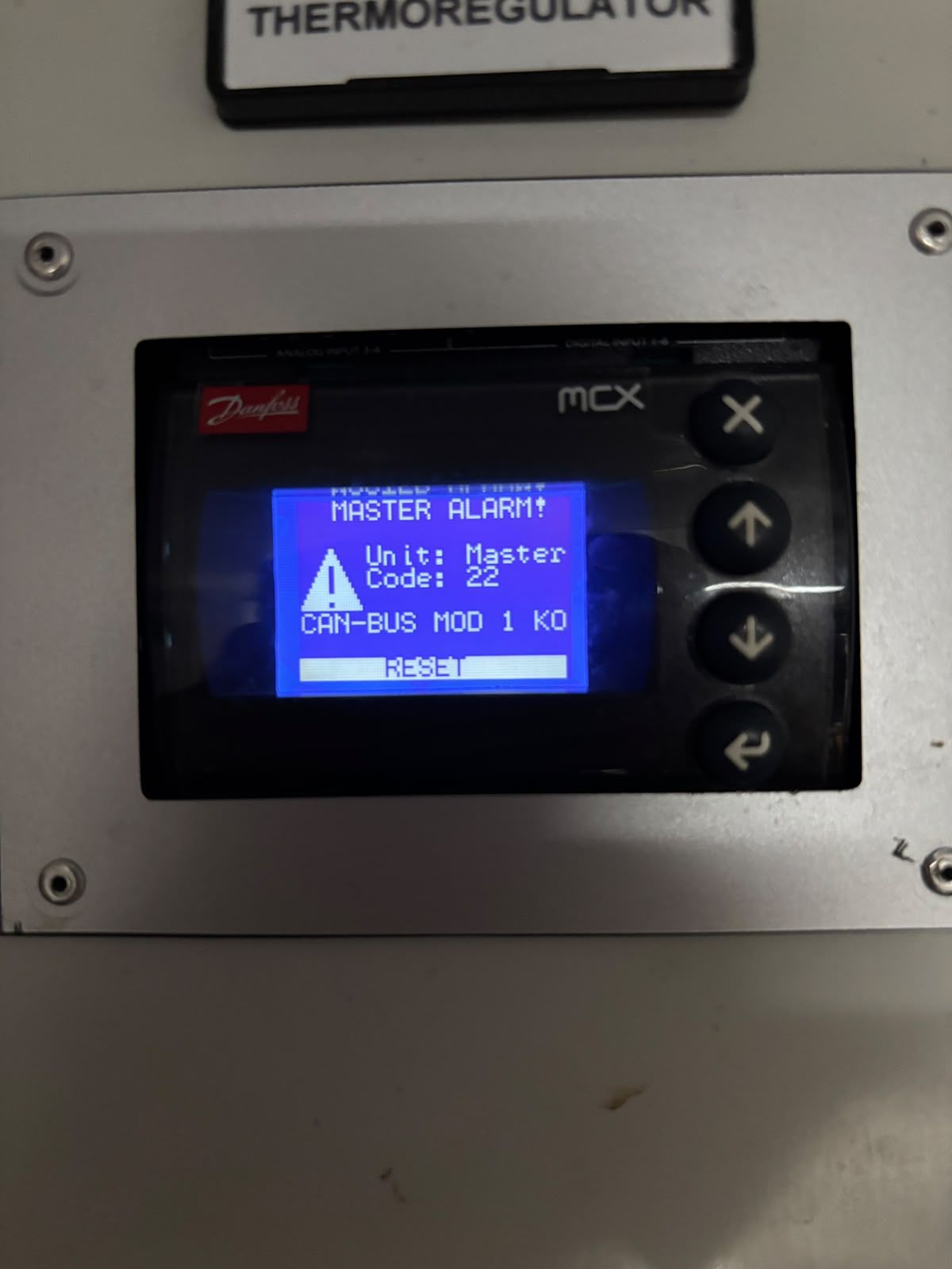
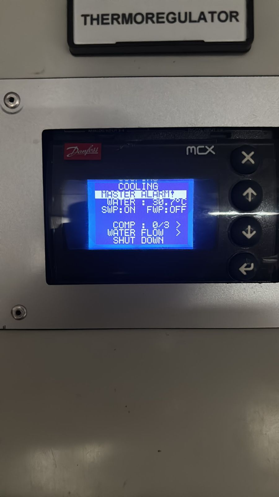
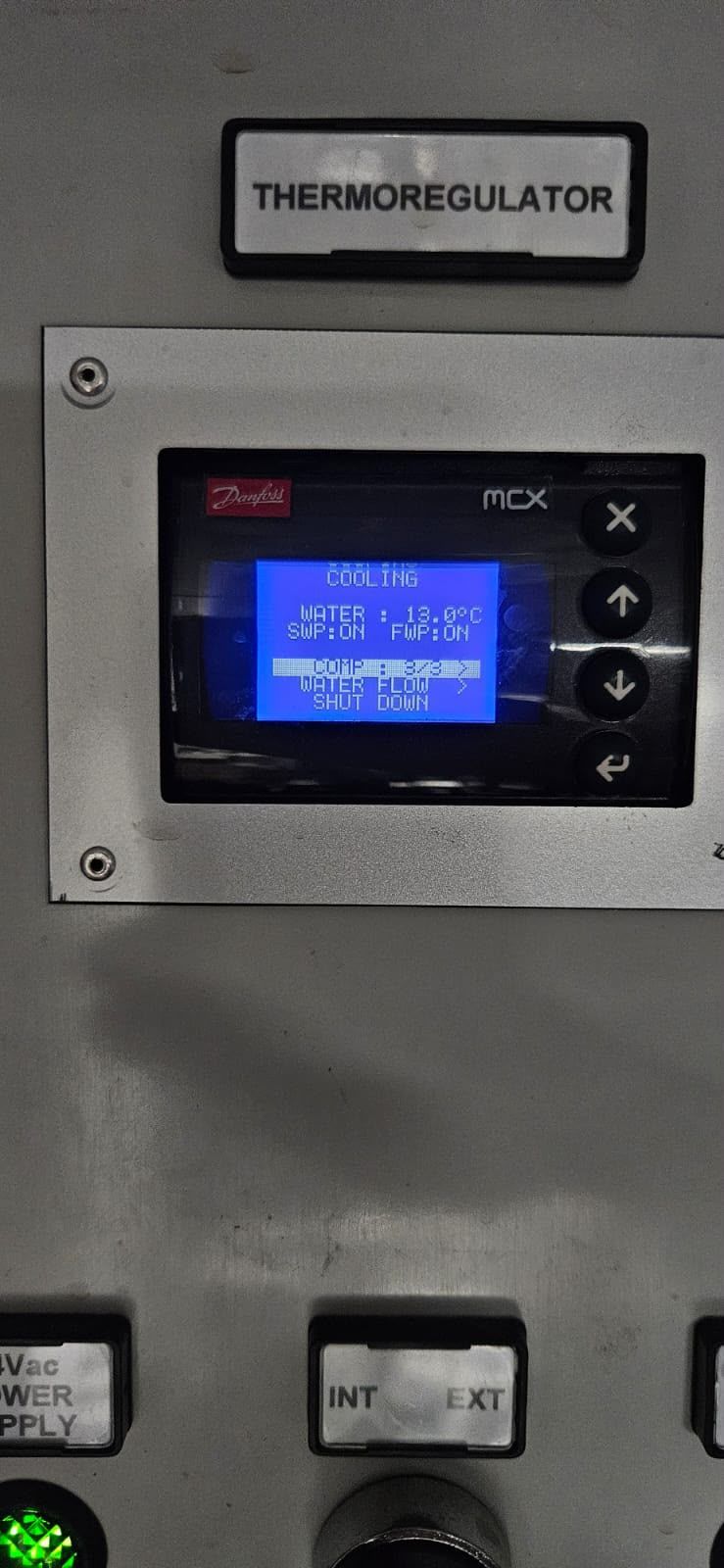
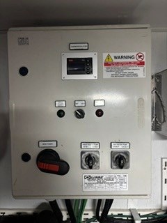
Photographed 7 Oct 2026. Danfoss MCX: MASTER ALARM, unit 1, code 30, DRIVE ALARM. Controller shows 02/01/2024 (controller clock known to be unreliable). Reading only, no cause implied.Photographed 7 Oct 2026. Danfoss MCX: MASTER ALARM, unit 2, code 30, DRIVE ALARM. Controller shows 02/01/2024 (controller clock known to be unreliable). Reading only, no cause implied.Photographed 7 Oct 2026. Danfoss MCX: MASTER ALARM, unit 3, code 30, DRIVE ALARM. Controller shows 02/01/2024 (controller clock known to be unreliable). Reading only, no cause implied.Photographed 7 Oct 2026. Event log: unit 1, code 22, CAN-BUS MOD 1 KO; logged date 27/07/2026 (clock setting not verified). Reading only, no cause implied.Photographed 7 Oct 2026. Event log: unit 2, code 52, FLOW METER ALARM; logged date 27/07/2026 (clock setting not verified). Reading only, no cause implied.Photographed 7 Oct 2026. Event log: unit 2, code 30, DRIVE ALARM; logged 11/08/2026 20:57 (clock setting not verified). Reading only, no cause implied.Photographed 19 Aug 2026. Event log: unit 2, code 23, CAN-BUS MOD 2 KO; logged 11/08/2026 20:33 (clock setting not verified). Reading only, no cause implied.Photographed 19 Aug 2026. Controller event log: unit 2 DRIVE ALARM, code 30 (logged date may be wrong; clock unverified). Reading only, no cause implied.7 Oct 2026. Active master-alarm list: unit 3 code 24, unit 2 code 23, unit 1 code 22. Reading only, no cause implied.7 Oct 2026. Active master alarm: unit 1, code 22, CAN-BUS MOD 1 KO. Reading only, no cause implied.7 Oct 2026. Controller main screen: MASTER ALARM, plant shut down.7 Oct 2026. Controller main screen: cooling water 13 °C, COMP 3 of 3, both pumps ON, as displayed. Reading only, no cause implied.14 Oct 2026 (as received). AC plant control panel, front: display and switches.
Shore power, transformer and earthing (35)
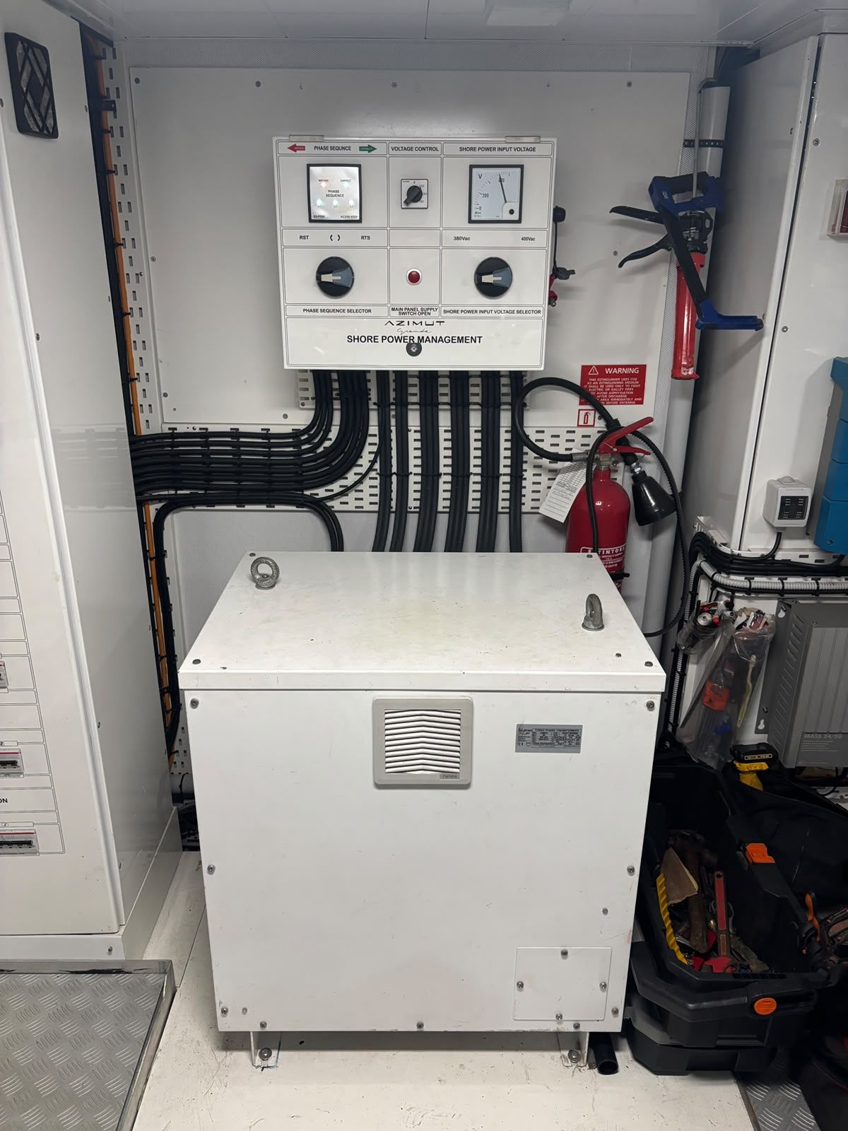
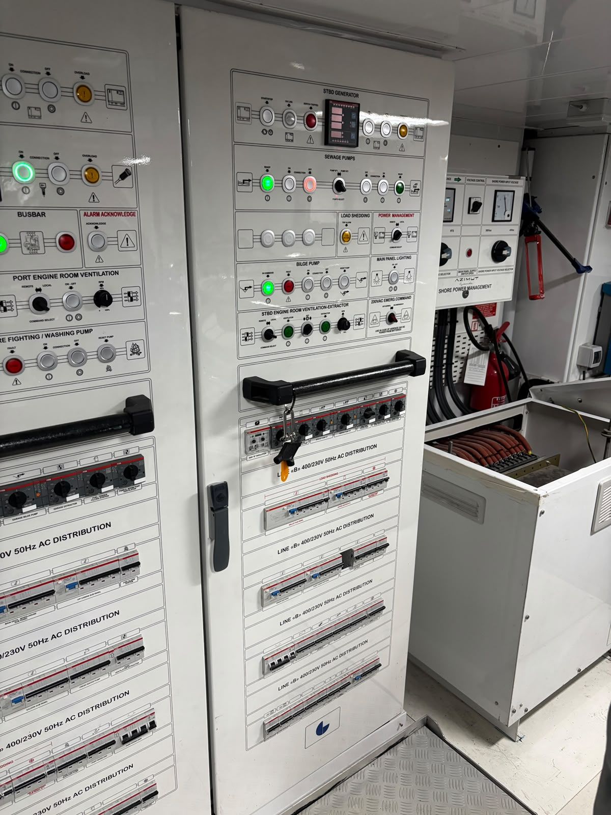
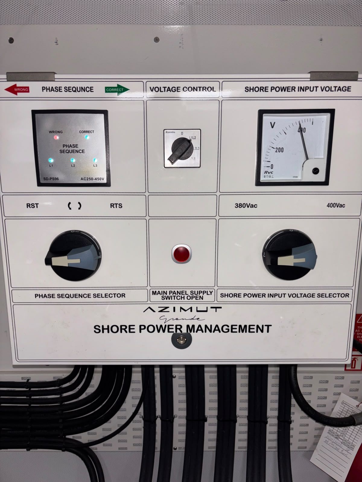
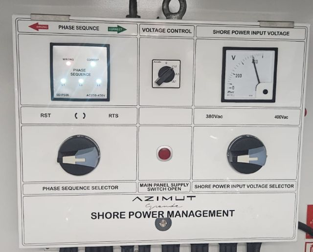
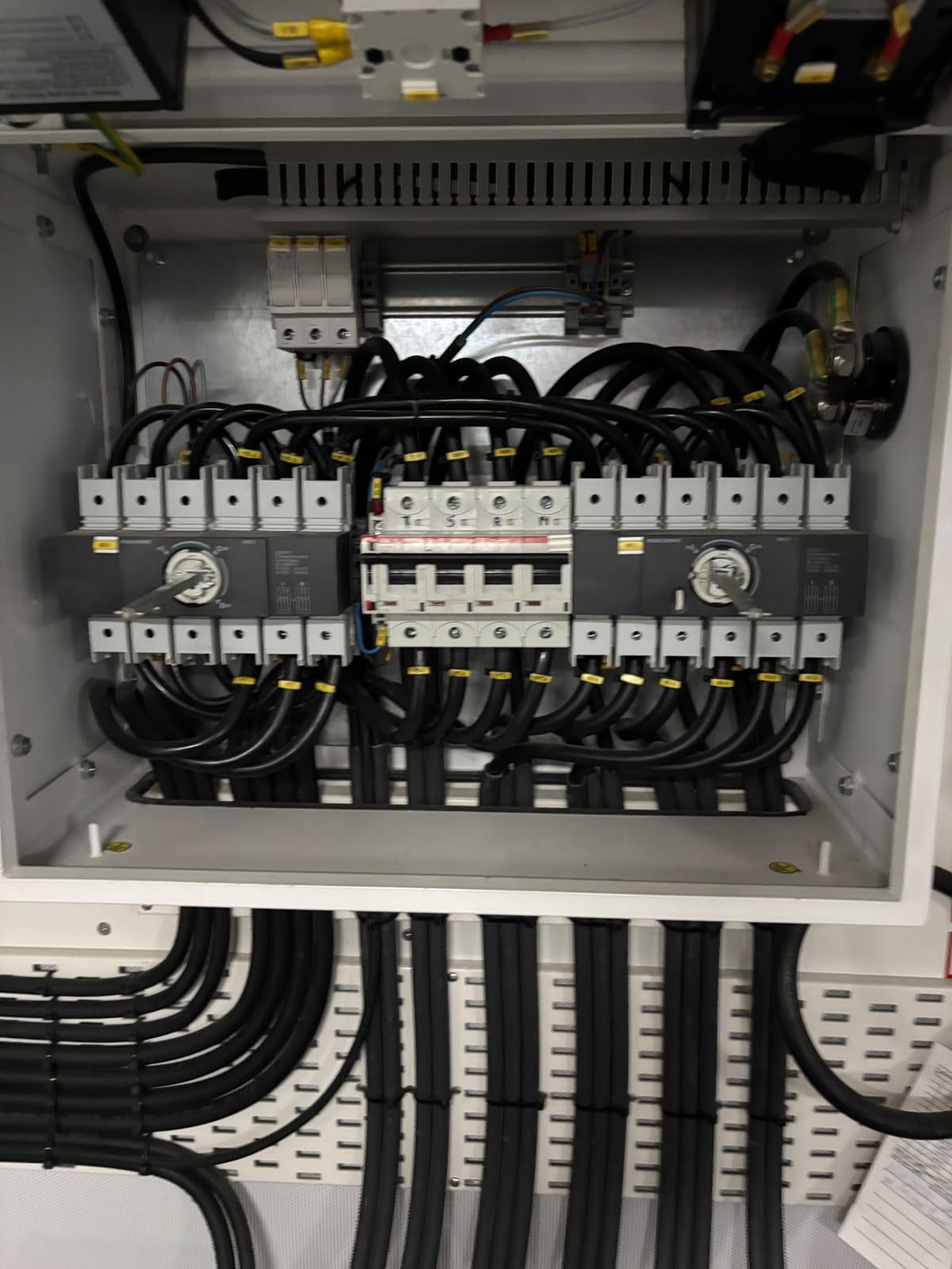
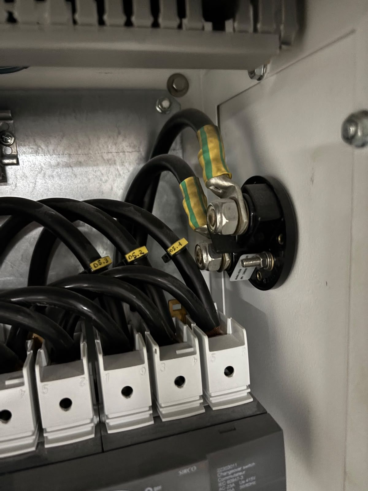
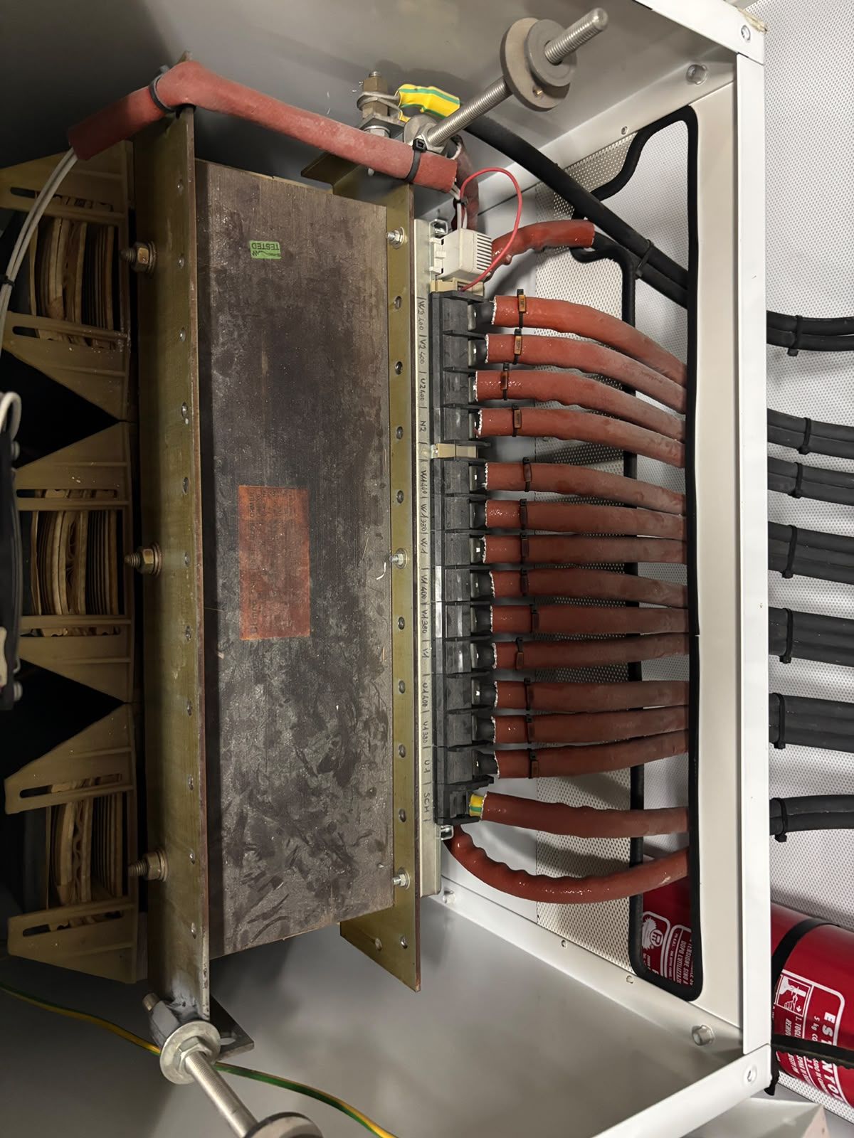
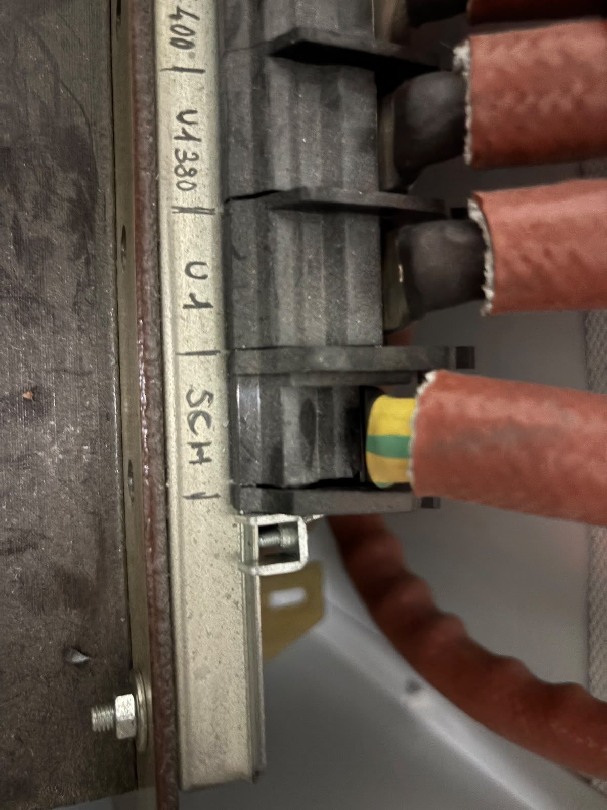
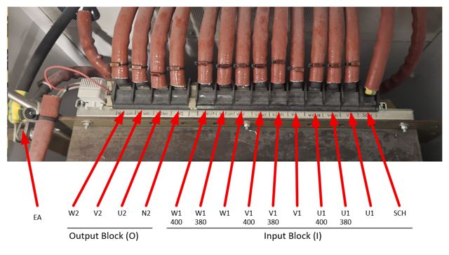
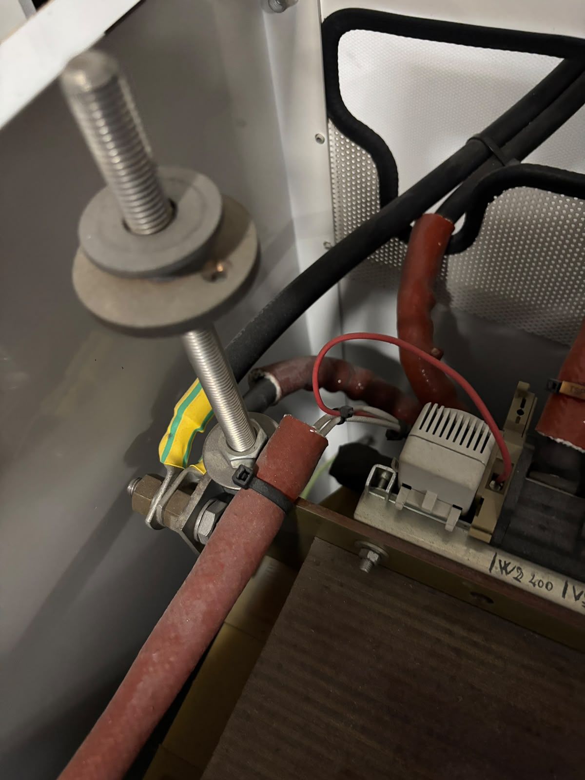
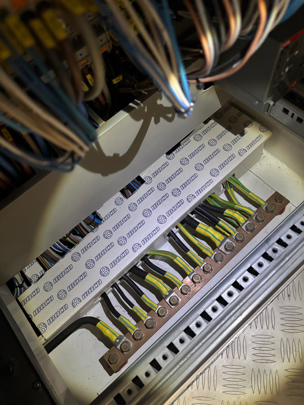
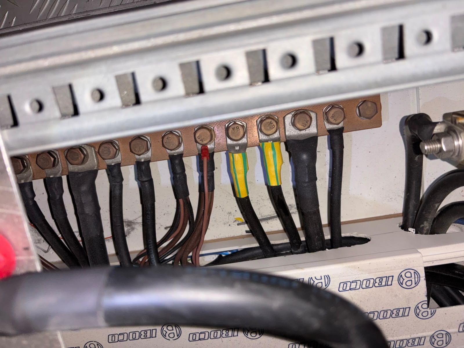
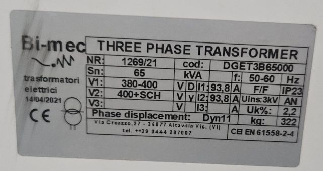
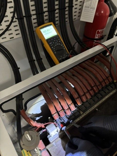
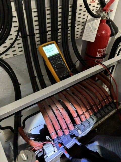
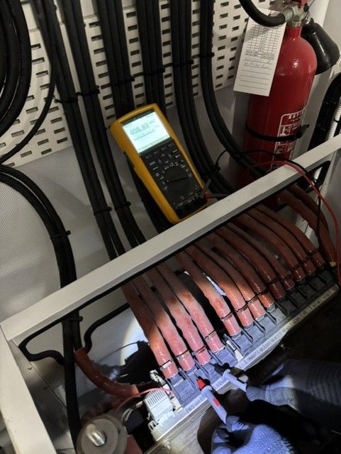
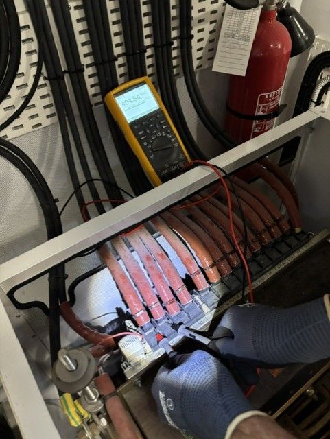
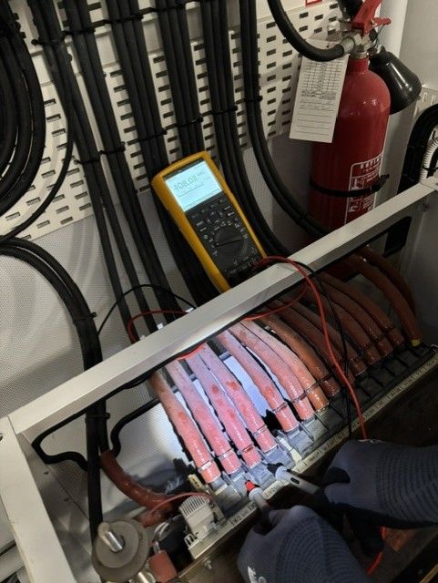
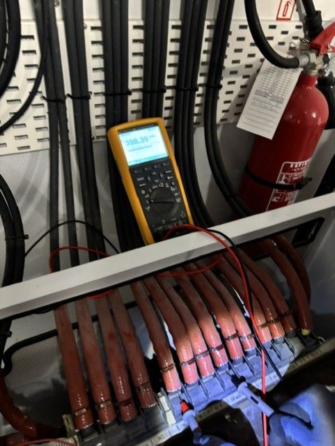
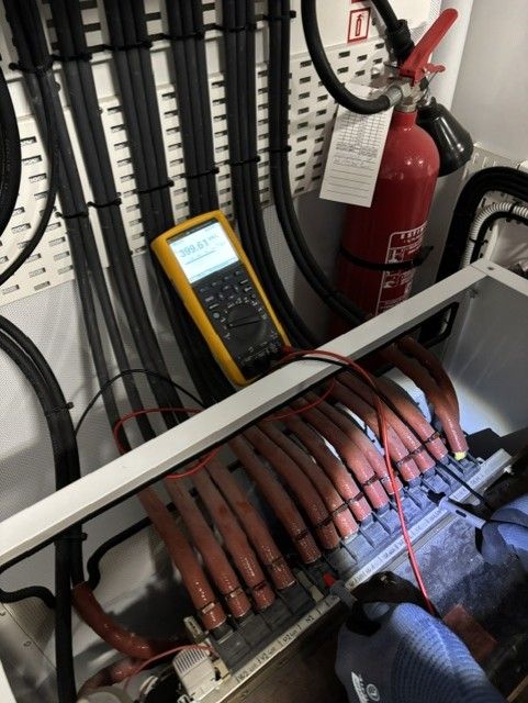
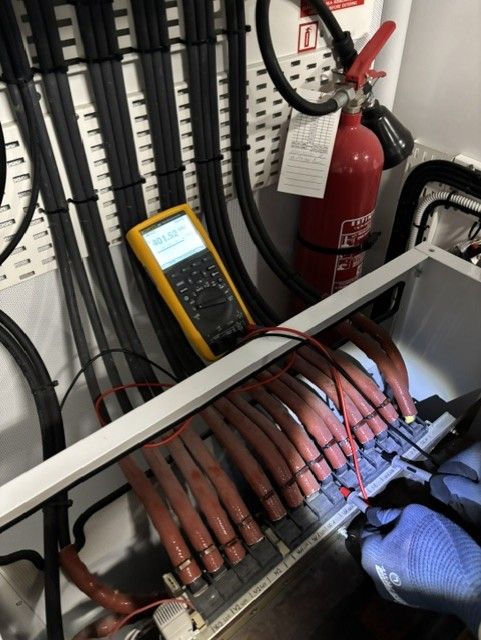
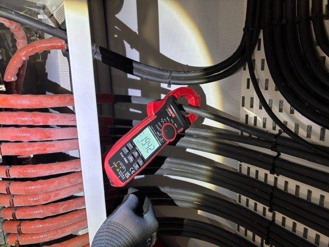
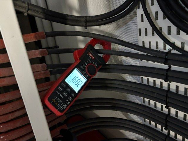
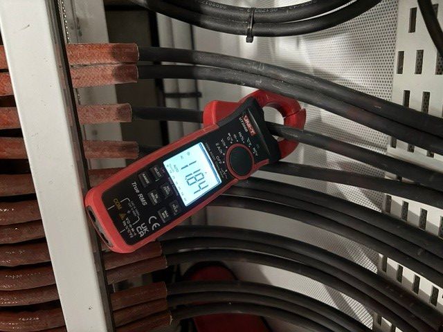
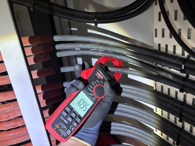
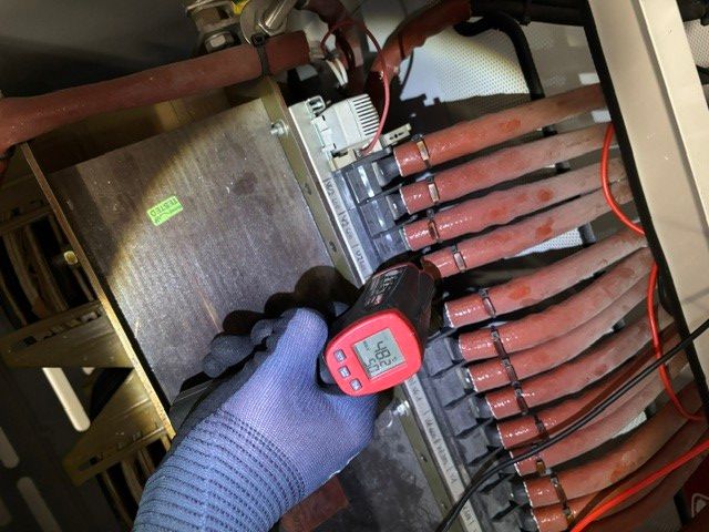
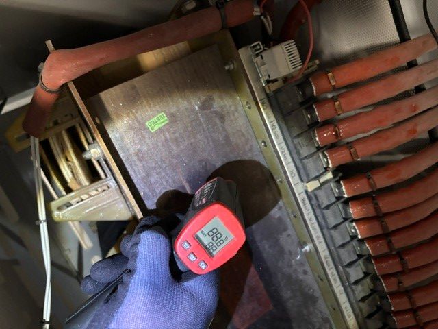
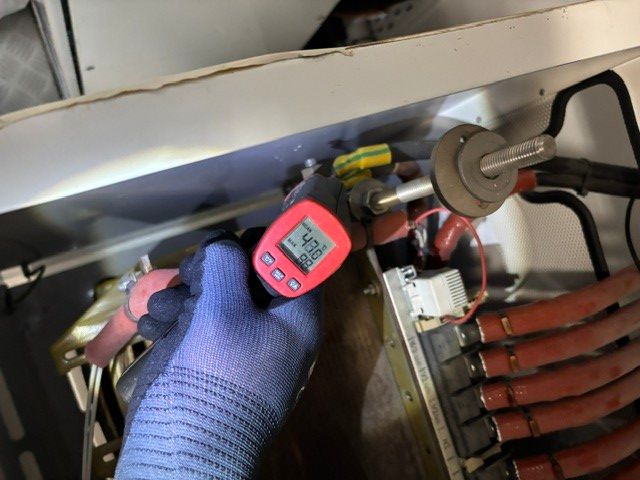
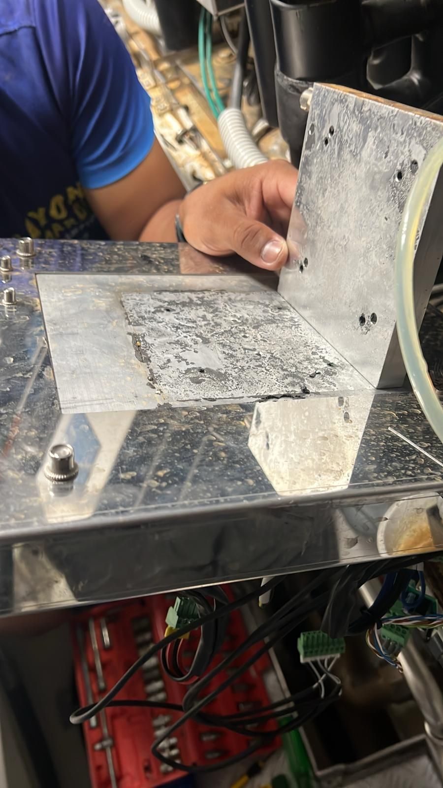
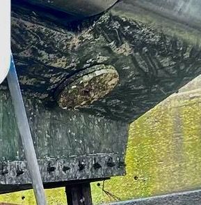
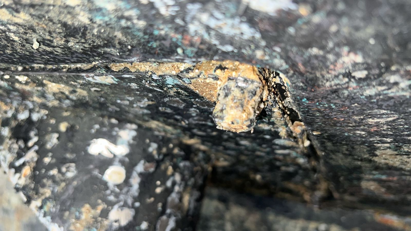
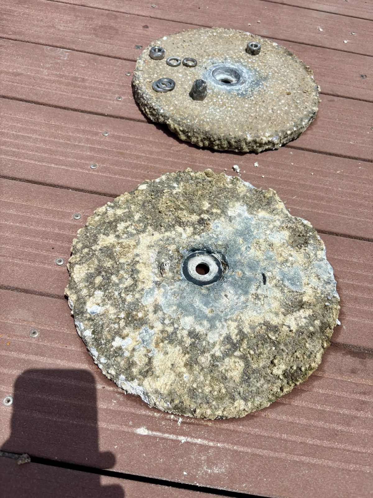
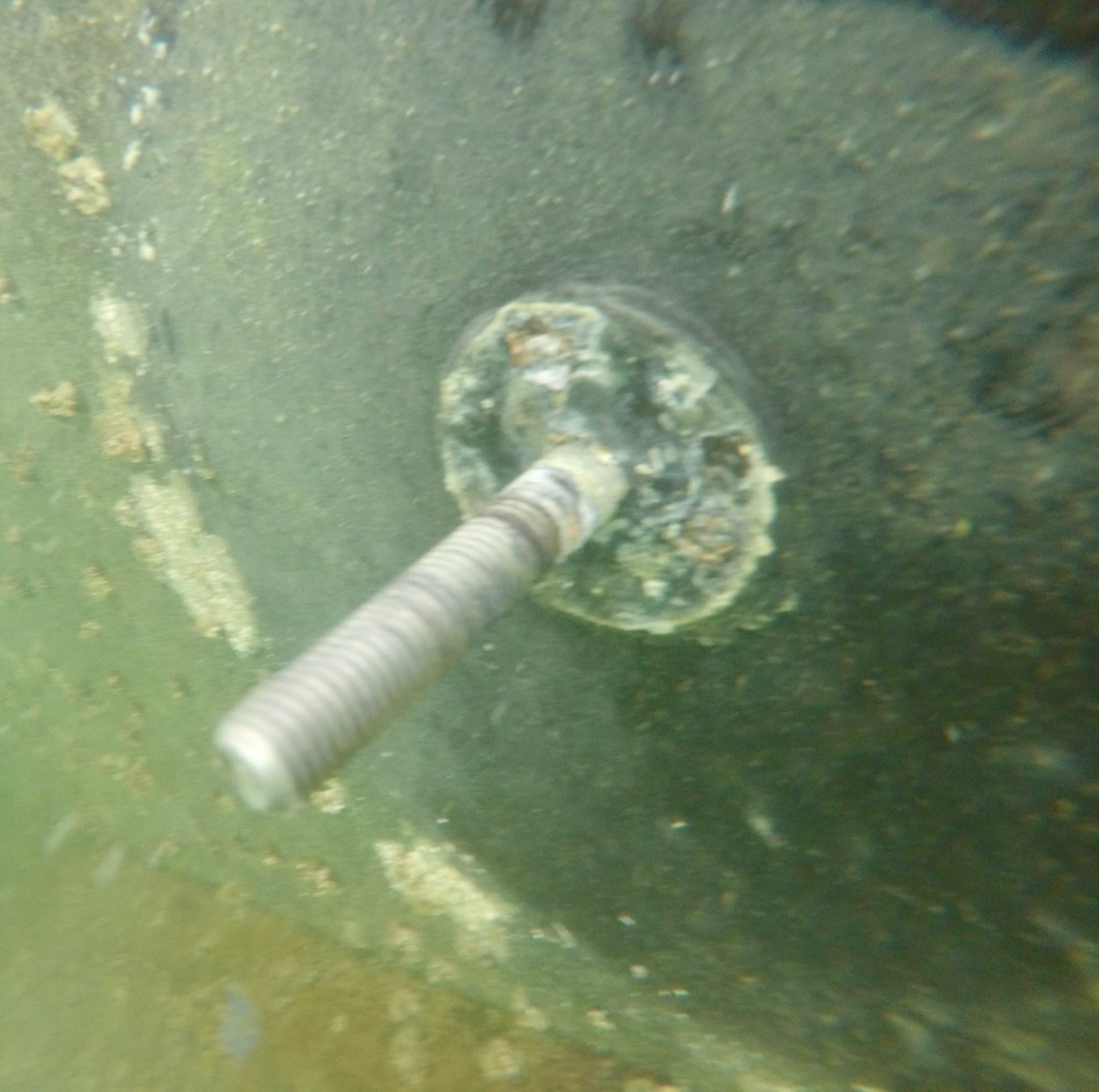
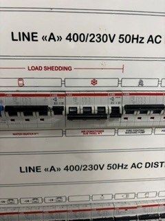
5 Aug 2026, 10:00. Shore-power compartment: management panel above the 65 kVA on-board isolation transformer.5 Aug 2026, 10:14. Main switchboard and shore-power compartment, general arrangement.5 Aug 2026, 10:00. Shore Power Management panel: WRONG phase-sequence lamp lit, voltmeter about 410 V as displayed. Reading only, no cause implied.3 Sep 2026. Shore Power Management panel: WRONG and CORRECT phase-sequence lamps both lit, selectors in the same position. Reading only, no cause implied.2 Sep 2026. Video (4 s, sound removed): shore input voltmeter switched across lines 1, 2 and 3, about 390–400 V each as displayed. Magnitudes only; does not show phase sequence. Reading only, no cause implied.5 Aug 2026, 10:09. Shore-power changeover cabinet: two 4-pole changeover switches and a 4-pole breaker.5 Aug 2026, 10:09. Changeover cabinet: earth feed-through stud with two green/yellow bonds.5 Aug 2026, 10:00. Isolation transformer with cover off: windings and terminal board.5 Aug 2026, 10:00. Isolation transformer terminal board: 380/400 V primary taps and SCH (screen) terminal.3 Sep 2026. Isolation transformer terminal board with labels added by the contractor: output W2 V2 U2 N2, input taps 380/400, SCH, EA.5 Aug 2026, 10:14. Isolation transformer frame earth bond: lug clamped to a stainless threaded rod.5 Aug 2026, 10:14. Main earth busbar from above, green/yellow bonds beneath the cable trunking.5 Aug 2026, 10:18. Main earth busbar close-up: copper bar and sleeved lugs.3 Sep 2026. Nameplate of the on-board shore-power isolation transformer (Bi-mec, 65 kVA, Dyn11).3 Sep 2026. Transformer output W2–V2 at minimal load: 407.81 V as displayed. Reading only, no cause implied.3 Sep 2026. Transformer output W2–U2 at minimal load: 409.76 V as displayed. Reading only, no cause implied.3 Sep 2026. Transformer output V2–U2 at minimal load: 408.87 V as displayed. Reading only, no cause implied.3 Sep 2026. Transformer output W2–V2 at 10–14 kW load: 404.54 V as displayed. Reading only, no cause implied.3 Sep 2026. Transformer output V2–U2 at 10–14 kW load: 408.08 V as displayed. Reading only, no cause implied.3 Sep 2026. Transformer input W1–V1 (400 V taps) at 10–14 kW load: 398.39 V as displayed. Reading only, no cause implied.3 Sep 2026. Transformer input W1–U1 (400 V taps) at 10–14 kW load: 399.61 V as displayed. Reading only, no cause implied.3 Sep 2026. Transformer input V1–U1 (400 V taps) at 10–14 kW load: 401.52 V as displayed. Reading only, no cause implied.3 Sep 2026. Clamp meter on output W2 at 10–14 kW load: 19.42 A as displayed. Reading only, no cause implied.3 Sep 2026. Clamp meter on output V2 at 10–14 kW load: 16.82 A as displayed. Reading only, no cause implied.3 Sep 2026. Clamp meter on output U2 at 10–14 kW load: 11.84 A as displayed. Reading only, no cause implied.3 Sep 2026. Clamp meter on neutral N2 at 10–14 kW load: 10.95 A as displayed. Reading only, no cause implied.3 Sep 2026. Thermal camera: transformer terminals about 48–50 °C at light load. Reading only, no cause implied.3 Sep 2026. Thermal camera: transformer core clamp plate about 89 °C at about 17% load. Reading only, no cause implied.3 Sep 2026. Thermal camera: transformer earth stud 47.0 °C as displayed. Reading only, no cause implied.11 Feb 2024. Metal plate removed near a bonding point in the machinery space.11 Mar 2025. Underwater view, possibly the rear transom anode (to be confirmed).11 Mar 2025. Sacrificial anode, showing wear and fouling (location to be confirmed).5 Sep 2026. Pair of transom anodes removed, with their mounting hardware.5 Sep 2026. Transom anode mounting stud, underwater close-up, anode removed.14 Oct 2026 (as received). Line A 400/230 V distribution board, with breakers grouped for load shedding.