Climma CWS MODUL 3603 chilled-water plant: technical facts
What this page tells you: what is broken in the AC plant, the measurements and every fault code, in plain English.
Root cause not determined; independent investigation sought. The facts below are recorded observations and measurements. No cause is asserted.
The system at a glance
Make, model and key ratings of the installed plant and its supply. Every value comes from a nameplate, a data plate, a service record or correspondence. Anything not yet verified is marked to be confirmed.
| Item | Installed | Source |
|---|---|---|
| Yacht | 2023 Azimut Grande 32m (hull 31), delivered June 2023 | Case brief; builder correspondence |
| AC plant brand | Climma by Veco (Italy) | Plant data plates; Veco dealer correspondence |
| Plant model | CWS MODUL 3603 RC 400/3/50 INV: three-module, water-cooled, inverter chilled-water plant. Veco part no. M91395RCYD. 3 × 120,000 BTU/h (about 360,000 BTU/h in total), ‘Gulf’ hot-climate option. The diagram also carries the code M91415YD (meaning to be confirmed) | Data plates, summarised in the Aug 2026 case file; manufacturer electrical diagram, order 7704, 15 Feb 2022 |
| Electrical (per module) | 400 V, 3-phase, 50 Hz; running current 11.2 A (cooling) / 13.8 A (heating); maximum 19 A | Data plate |
| Electrical supply to plant | Main switch 6-pole 63 A; one 3-pole 25 A C-curve breaker per module; control circuit 24 V AC via a 50 VA transformer; enclosure IP40; short-circuit rating 6 kA | Manufacturer electrical diagram, order 7704, 15 Feb 2022 (received 12 Oct 2026) |
| Compressors | 3 (one per module), hermetic, inverter-driven (variable speed), R410A. Make and model: to be confirmed (compressor nameplate not yet recorded) | Service photos; compressor test record, 29 May 2026 |
| Inverter drives | Climma/Veco inverter boards, one per module. Board types recorded: FM623A (software V4.02), FM624 / FM625A; the twice-replaced unit 3 board is type FM632A. IGBT power module: Semikron SKiiP 24NAB12 (label photo). Board type for each unit: to be confirmed | Independent inspection, 29 Jun 2026; Aug 2026 photos; service quote, Feb 2026 |
| Line reactors | Martignoni, three-phase, 40 A, 0.4 mH, one per module, in the Veco inductances box (M8281OY) (nameplate photo) | Nameplate photo; independent inspection, 29 Jun 2026 |
| Controller / HMI | Danfoss MCX master controller (MCX06D) with display, linking modules 1–3 over one CAN bus (screen photo). The CAN bus is terminated with a 120 Ω resistor at both ends of the chain (per the diagram; termination on board: to be confirmed). Inputs: flow switch, chilled-water inlet temperature sensor, remote alarm, remote emergency stop, cool/heat selector. Controller firmware version: to be confirmed. Controller clock: not verified | Controller screen and event-log photos, Jul–Aug 2026; Manufacturer electrical diagram, order 7704, 15 Feb 2022 (received 12 Oct 2026) |
| Refrigerant | R410A, 4.250 kg per module | Data plate |
| Chilled-water loop | Closed fresh-water and glycol loop; about 6 m³/h per module. Refilled at about 30% glycol in Feb 2024; a sample taken on 25 Jun 2026 was clear, with glycol present (sample photo). Current glycol concentration: to be confirmed. Pumps: 2 chilled-water pumps, duty/standby selector, design rating 3 kW (about 6.6 A), motor protection 3–12 A (per the manufacturer diagram, order 7704). Make and model: to be confirmed | Service report, Feb 2024; sample, 25 Jun 2026; dealer email, Jun 2026 |
| Seawater (condenser) loop | About 6 m³/h per module; 2 seawater pumps, duty/standby selector, design rating 1.1 kW (about 2.9 A), motor protection 1.25–5 A (per the manufacturer diagram, order 7704); one replaced in 2024 after seizing. Pump make and model: to be confirmed | Data plate; captain’s email, 24 Jun 2026 |
| Fan coils | Climma fan coils; one saloon unit is 24,000 BTU, and an EVA17/C16 blower assembly was replaced in Feb 2026. Model of each unit and total quantity: to be confirmed | Service report, Feb 2024; service record, Feb 2026 |
| Shore-power isolation transformer | On board, always in circuit: Bi-mec, 65 kVA, Dyn11, primary 380–400 V, secondary 400 V, EN 61558-2-4, dated 14 Apr 2021 (nameplate photo) | Nameplate photo; shore-power survey, 5 Aug 2026 |
| Generators | Kohler 55EFOZDJ, 50 Hz. Number of sets: to be confirmed | Captain’s email, 24 Jun 2026 |
| Shore supply | Marina supply, 400 V, 3-phase, 50 Hz; the panel read about 405–415 V on 5 Aug 2026. Shore connection rating: to be confirmed | Shore-power survey, 5 Aug 2026 |
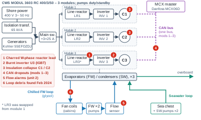
Schematic (owner's simplified summary, not as-built, not a manufacturer drawing)
Power path
- Shore power (400 V, 3-phase) or generators
- On-board isolation transformer (65 kVA)
- Plant main switch (6-pole 63 A), then one 25 A breaker per module
- Each module: line reactor 1 → inverter drive 2 → compressor C1/C2/C3 3
Control
- Danfoss MCX master controller (MCX06D, single master) talks to modules 1–3 over one CAN data cable, terminated at both ends 4
Water loops
- Chilled fresh-water loop (with glycol): evaporators → fan coils in cabins → FW pumps (2, duty/standby) → flow sensor 5; debris found Feb 2024 6
- Seawater loop: sea chest and SW pumps (2, duty/standby) → condensers → overboard
Power runs from shore power or the generators, through the on-board isolation transformer, to each module's line reactor, inverter and compressor. The controller talks to all three modules over one data cable (CAN bus). Open the drawing full size to zoom. Red markers: 1 charred W-phase reactor lead (unit 3); 2 burnt inverter (unit 3); 3 compressor insulation failures (C1, C2); 4 lost controller contact (modules 1–3); 5 flow alarms (unit 2); 6 debris in the loop, Feb 2024.
Key measurements
| Item | Result |
|---|---|
| Insulation to earth, 29 May 2026 | C1 109–110 Ω | C2 23.5–23.8 MΩ | C3 3.2–3.4 MΩ |
| C2 insulation, 19 Aug 2026 | ~5.6 Ω on all phases (from 23.5 MΩ on 29 May) |
| Windings (L–L) | Balanced: 1.43–1.53 Ω all units (29 May); C2 1.8 / 1.9 / 1.8 Ω (19 Aug) |
| Line reactor U3 (29 Jun) | U 0.2 / V 0.2 / W 2.7 Ω (two-wire readings; values below 1 Ω indicative only; four-wire test pending); 1W lead charred, 1V lead blackened, terminal housing heat-browned |
| Inverter U3 (29 Jan) | IGBT scorch and PCB charring; cooling plate bright |
| AC leakage current test (Sep) | AC 0.33–0.51 mA; AC 72 mV shore → 4 mV; plant off during test |
| Hull potential / bonding | −0.981 to −1.003 V Ag/AgCl (protected); galvanic 79 / 65.5 mA; transom anode continuity ~3 Ω |
| Shore supply / transformer | Unbalance <0.5%; no hot joints; neutral 10.95 A with triplen harmonics; phase-sequence lamp reads “WRONG” |
Controller fault codes (Danfoss MCX), with plain-English meaning
Logged dates are indicative. The controller logged the 19 Aug 2026 event as 11/08; the controller clock setting has not been verified. Code 30 sub-code decodes have not been confirmed by the manufacturer.
| # | Date | Unit | Code | Screen text | Meaning (C859-05) | In plain English |
|---|---|---|---|---|---|---|
| 1 | 02-01-24 07:51 | 3 | 30 | DRIVE ALARM | Inverter alarm, sub-code 3: inverter overheating | The drive for compressor 3 got too hot and shut down |
| 2 | 02-01-24 08:18 | 3 | 30 | DRIVE ALARM | Inverter overheating | Same again, 27 minutes later |
| 3 | 02-01-24 09:01 | 2 | 30 | DRIVE ALARM | Inverter overheating | The drive for compressor 2 got too hot |
| 4 | 02-01-24 10:14 | 1 | 30 | DRIVE ALARM | Inverter overheating | The drive for compressor 1 got too hot: all three drives overheated within about 2.5 hours |
| 5 | 03-03-24 | 2 | 7→52 | Low fresh water flow / repeated flow alarm | Low FW flow, then 4th repeated flow alarm | Water stopped flowing properly through module 2, repeatedly |
| 6 | Aug-24 | plant | — | Whole-plant shutdown | Reported as CAN communication fault; code not recorded | The whole plant stopped; reported as the controller losing contact with the modules |
| 7 | 13-12-25 | 1, 2 | — | DIS-VOLT state, ~30 s after start, no alarm logged | Not a code; matches Code 30 sub-code 10 “temporary undervoltage ×3 – DISUV” | Drives saw a brief low-voltage dip three times just after start; no alarm was saved |
| 8 | May-26 | plant | — | Shutdowns incl. display, no alarm logged | No code | The plant, including its display, switched off with no alarm saved |
| 9 | 27-07-26 00:49 | 1 | 22 | CAN-BUS MOD 1 KO | Missing CAN communication, module 1 | The controller lost contact with module 1 |
| 10 | 27-07-26 02:24 | 2 | 52 | FLOW METER ALARM | Repeated FW flow alarm (4th) | Module 2 water-flow alarm, fourth repeat |
| 11 | 27-07-26 02:34 | 2 | 52 | FLOW METER ALARM | Repeated FW flow alarm | Module 2 water-flow alarm again |
| 12 | 29-07-26 11:34 | 2 | 7 | FLOW METER ALARM (autoreset) | Low FW flow; flow 6.71→0.00 m³/h, plate 62.3 °C | Module 2 water flow dropped to zero and its drive plate reached 62.3 °C |
| 13 | 11-08-26 17:08 | 2 | 23 | CAN-BUS MOD 2 KO | Missing CAN communication, module 2 | The controller lost contact with module 2 |
| 14 | 11-08-26 20:33 | 2 | 23 | CAN-BUS MOD 2 KO | Missing CAN, module 2 | Lost contact with module 2 again |
| 15 | 11-08-26 20:34 | 2 | 30 | DRIVE ALARM | Inverter alarm, sub-code 1: inverter over-current | The module 2 drive saw too much current |
| 16 | 11-08-26 20:57 | 2 | 30 | DRIVE ALARM | Inverter over-current | Too much current again on module 2 |
| 17 | 19-08-26 12:54 | 2 | 23 | CAN-BUS MOD 2 KO | Missing CAN, module 2 | Lost contact with module 2 |
| 18 | 19-08-26 | 2 | 23→30 | — | Missing CAN mod 2, then inverter over-current; ~5.6 Ω phase to earth measured | Lost contact, then too much current; compressor 2 then measured as shorted to earth (about 5.6 Ω) |
| 19 | undated | 3 / 2 / 1 | 24 / 23 / 22 | Active alarm list | Missing CAN, modules 3, 2 and 1 – all three off the bus | None of the three modules was talking to the controller |
| 20 | undated | master | — | MASTER ALARM, water 30.7 °C, FWP OFF, COMP 0/3, WATER FLOW SHUT DOWN | Plant shut down on FW flow, no compressors | The whole plant stopped because water was not flowing; no compressors running |
Photos


More: all photos · glossary · the full story step by step.
Documents being sought
- Manufacturer electrical diagram for the CWS MODUL 3603 RC: received 12 Oct 2026.
- Installation manual for the installed model (the manual on board is for CWS MODUL 2402).
- Yacht-side installation wiring, earthing and bonding drawing.
- Controller parameter file and firmware version.
- Manufacturer commissioning remarks list.
- Factory chilled-water fill and glycol record.
Open questions
- What was the initiating cause, and in what sequence did the failures occur?
- Can the existing compressors, drives and reactors be repaired?
Frequently asked questions
What fault codes did the Danfoss MCX controller log?
The log includes Code 30 inverter alarms, CAN-bus and flow alarms; the full record is in the fault-code table on this page. Logged dates are indicative because the controller clock setting has not been verified, and Code 30 sub-code decodes have not been confirmed by the manufacturer.
Which documents are being sought?
The manufacturer electrical diagram for the installed CWS MODUL 3603 RC was received on 12 Oct 2026. Still sought: the installation manual for the installed model, the yacht-side installation wiring, earthing and bonding drawing, the controller parameter file and firmware version, the manufacturer commissioning remarks list, and the factory chilled-water fill and glycol record.